AGC on BJT amplifier, how to?
Two ways as I see it, 1, is to include a diode in series with the earthy end of C12, as the current increases in this diode, its impedance falls and more voltage is dropped across the transformer. the other way is to reduce the bias on Q5 and Q6 by returning R12 to a slightly negative supply. It all depends on the amount of control and distortion you want. The other way is to build a current controlled diode attenuator on the output.
Frank
Thank you for the answer.
I have previously built a voltage divider at the output using a resistor and a FET and there was no visible distortion at the output. This worked well. However I manually set the gain of the fet by applying manually voltage to the gain. I could not make it automatically adjust it's gain without distorting, any ideas are appreciated about this.
I will also try the things you mentioned.
Saying you want no distortion makes clear that "AGC on BJT amplifier" won't work. A variable FET attenuator is basically a good idea, it won't give considerable distortions if designed right.
I think that it would be however preferable to implement a level control for the oscillator itself, in case of doubt it should further improve the frequency stability.
Thank you FvM,
In order to see the distortion of the fet variable attenuator, I have just made a small page with another oscillator for testing.
This is exactly the same as the oscilaltor in post #1 and the only difference is that it uses a fet instead of a bjt for the oscillator.
I have tried a FET attenuator at the output of the oscillator (buffer has not built yet) and it works without noticeable distortion on the scope, by manually applying voltages to the gate.
I have used this AN for the attenuator http://www.vishay.com/docs/70598/70598.pdf
My problem is that I do not know how to derive the voltage needed for the gate, so that an AGC effect is caused by the attenuator.
Also, what is this level control for the oscillator you refer to?
To keep the linearity of a BJT stage controlled by AGC it is a challenge.
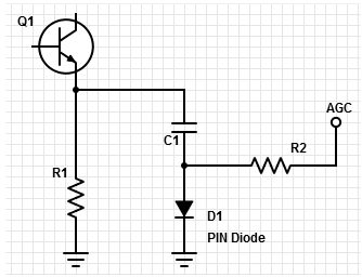
The circuit below (which would change the decoupling value of the decoupling emitter capacitor), would have a minimum effect on the linearity of the stage, because the DC bias of the amplifier is not affected.

A control voltage has to derived for any kind of attenuator, in so far the problem isn't specific to FET I think.
If you use a feedback controller for level control, you don't need to know the exact control characteristic and can tolerate threshold voltage variations of the FET.
The oscillator has a variable supply voltage through Q2, I think it's the right place to apply level control.
Oh I forgot to post the link of the new oscillator I was referring to.
http://qrp.gr/lnosc/index.htm
I have tried taking the voltage from rectifying the output signal before the attenuator, with a set of diodes (negative). Then this voltage drives the fet attenuator after it. It did not work and the signal was distorted.
So you mean controlling the whole oscillator operating voltage?
Failure of your attempt doesn't mean that the methode doesn't generally work, apparently the design wasn't well considered.
One point is that your design obviously doesn't implement a feedback topology, otherwise the level after the attenuator would be sensed. I presume you know how a receiver AGC works.
- Delayed AGC implementaion and Noise figure measurement of Receiver with AGC
- Adding AGC to high gain AF amplifier
- HF broadband AGC signal amplifier schematic needed
- Using microphone preamplifier IC with AGC to amplify Schottky diode mixer output?
- Helo on getting data with its description of an AGC example
- 2sc1589 and S10-12 vintage BJT packages?
