FM transmitter filter
I checked some FM circuits over internet and all seems to miss the band pass filter at the last stage.
This make circuit transmits on all radio channel which is not something nice from my point of view
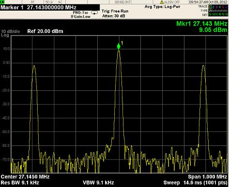
This circuit operates at 27 MHz and you can see the frequency domain and harmonics on the side of the middle peak

I was thinking about adding some filtration process before the antenna.
I only found a circuit that has filtration process at the end :
I would need to modify the L and C values so I can use it in the FM ranges (88-108 MHz)
would this idea work or i need more filteration stages?
Dear mr_byte31,
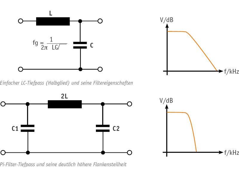
The circuit you posted in my opinion works as a impedance matching and as band pass filter too, however, it does not have a very good rejection to other frecuencies. I think you could try with a low pass filter. An easy filter to do which has good rejection for upper frecuencies is the Pi filter, it has only 3 passive parts (two variable capacitors and one coil) with a Pi filter you could have around of 20 to 26dB of rejection for 2nd and 3rd harmonic frequency.
I hope you can solve your question.
Have a nice day.
Best regards,
Juan
Spectrum analyser display, centre frequency = 27 MHZ, spurious signals at 27 MHZ +- 4 MHZ, where do these come from? then you say use a filter at 100 MHZ. Does not make any sense?
Frank
Hi Frank
The side peaks is due to the FM modulation , this is a common thing since FM follows Bessel functions.
REF : http://www.radio-electronics.com/inf...-sidebands.php
My figure for the filter is from another circuit , i was just showing the connection :) sorry if this confuses you
Hi Juan,
PI filter seems a nice option but it seems a LP :) , should I add another HP after it ?

As your Fm modulation frequency is 4 MHZ, you need to maintain a wide flat bandwidth. I would just go for shunt series tuned circuits to short out harmonics of Fc ( X2,X3 ?).
Fraank
Picture of Operational Amplifiers:
Frank, I think the span is 1MHz total, not 1MHZ/div
Yes. Looks like a stable ≈400 kHz modulation rather than spurs.
Yes I see, makes more sense now !
Frank
you mean something like that :

