Patch array antenna E-plane and H-plane orientation confusion in datasheets.

Also i refer to this(1): http://www.thefullwiki.org/Patch_antenna/ there is an image of patch antenna. And this(2): http://www.rfglobalnet.com/doc/the-b...-antennas-0002
Also famous "E plane is the plane in which the electric filed is dominant".
As i understand E-plane is coincides with feeding line and perpendicular to radiating edges. Also E-plane perpendicular to patch itself.
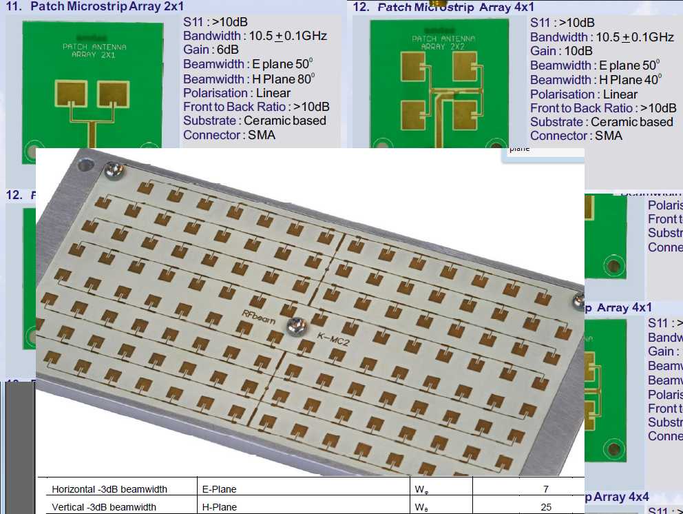
Now i am looking at big patch array (white one): E-plane 7deg H-plane 25deg. But from image i can see that more elements is placed along H-plane, so H-plane must be 7 deg, and it is more likely that E-plane is 25deg.
Now green antennas:
Left one E-plane 50deg H-plane 80deg
Right one E-plane 50deg H-plane 40deg.
As we can see E-plane of both green antennas is 50deg, so it must be horisontal plane, as in-phase patches number is directly affect angle. But horisontal plane is H-plane from what i learned (http://www.antenna-theory.com/antenn...es/antenna.php "Hence, the fringing E-fields on the edge of the microstrip antenna add up in phase and produce the radiation of the microstrip antenna.")
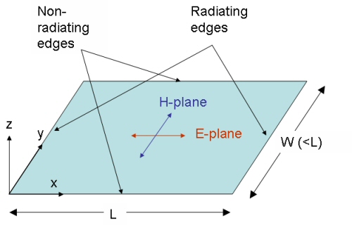
Here is final image that confuses things ever more:

(image from http://www.microwaves101.com/encyclo...nna_ustrip.cfm)
From this image we see that H-plane is perpendicular to feeding line, while E-plane is parallel with feeding line. Both planes perpendicular to PCB patch plane. If we look again at amitec and rfbeam images then E-plane and H-plane position does not match this image.
Please explain me what's wrong here?
Hello,
First off, take this with a grain of salt, perhaps someone with more experience can chime in. I don't agree with the figures in microwaves 101.
It always helped me to view these patch antennas as back to back quarter wave transmission lines. For a single patch the E-plane represents where there is virtual electric wall, the plane where the two quarter wave lines meet back to back. More generally, E-planes represent where the E-field is perpendicular to a plane or boundary condition (like a conductor). The "radiating edges" are the points where the E-field is at a maximum and indicates the open end of the transmission line. In my opinion the E-plane would be parallel to the radiating edges.
The H-plane works the same way, but the duel of the problem. For a patch antenna the H-plane represents where the H-fields are perpendicular. The current flows along the non-radiating edges with a maximum where the two back to back t-lines meet and a minimum at the end of the open circuit. I would say the H-plane is perpendicular to the radiating edges.
Hope that helps,
Sami
I agree that they mislabeled the E and H plane on the large array.
thank for the replies! still very confusing, as it still two different opinions.
I found one more article http://www.mathworks.com/examples/aa/4388-polarization-analysis-for-an-x-band-microstrip-patch-antenna
in this article e-plane is parallel to feeding line (coaxial feed is identical to inset feed). On the white and green patch arrays in the first post this plane is called h-plane.
I didn't read the original question well enough. I feel I caused more confusion than help, sorry for that. I was referring to e-plane splits and symmetry within the patch itself. In the case of radiating e-plane I agree with edf above. The e-plane for microstrip patches lies perpendicular to the radiating edges where the fringing fields on either edge of the patch point in the positive X (for that pic) direction and add in phase in the far field.
I've done a quick simulation for you where E and H field orientation is visualized (field plot at some distance above the patch):
E field:

H field:

E field is voltage , H field is current and with matched impedances, both will be high except where fringing effects or interference patterns exist.
for impedance Transformer type antenna , a higher current drive lower source will create more dominant E fields which more gain to combat E field path loss is preferred . But for near field antenna like magnetic loops, just the opposite, like MRI.
this is also related to why conducted EMI noise tests are current up to 30MHz antenna and broadband E field dominant above this, but in an ideal transmission line path, both exist.
.. Hand waving argument...
Refers to antenna pattern in two planes where the 'E' field plane is parallel to what is normally referred to polarization plane, like vertical and horizontal polarized antenna.
For example, a 5/8 wavelength vertical monopole antenna perpendicular to earth is normally referred as a vertically polarized antenna. 'E' plane would normal quoted pattern which is a circle in birds eye view. 'H' plane would be pattern in earth to sky plane which has a dominate lobe to horizon and secondary lopes at higher angles relative to earth plane. 'H' plane pattern would not normally be of interest to this type of antenna, unless antenna was used to communicate with airplanes or orbiting spacecraft.
An ideal GPS antenna pattern would be a uniform hemisphere (upside down bowl) radiation pattern with equal gain to all points at angles greater then plane of earth in all horizon (north, south, east, west) directions. This ideal GPS antenna would have identical 'E' and 'H' plane patterns.
A feed point for a symmetrical parabolic dish should have same pattern for all equal spherical angles to the dish surface. A rectangular waveguide to flare horn feed would have an unequal radiation pattern across the dish surface. The feed horn would have a different pattern beamwidth for 'E' and 'H' planes.
I still have question why E and H planes are messed up in many places (just googled for E-plane H-plane patch antenna arrays):
1) http://www.emfield.org/icctadmin/dow...per.php?id=818 (http://www.emfield.org)
In this paper we can see 14 x 6 patch array. Feeding lines goes to patches from bottom side, so i E-plane must be vertical. It is 6 patches direction, and beam is wider than in horizontal direction. But from fig.8 we can see, that E-field pattern is narrower than H-field pattern!
2) http://www.rfbeam.ch/fileadmin/downl...eet_K-LC1a.pdf (http://www.rfbeam.ch/)
Here is 1x4 element patch array. Feeding lines from the bottom side of patches. Again guessing E-plane is vertical. There is 4 patches in vertical direction and only one in horizontal, so guessing that horizontal (H-plane) beam is wider than vertical (E-plane) beam. It is true if we look at fig.2. But in characteristics on page 3 it is written that E-plane is horizontal! Again messed up.
3) http://www.ic72.com/pdf_file/n/93458.pdf (http://www.ic72.com/)
Here and many other x-band doppler modules like HB100. In datasheet we can see that E-plane is narrower than H-plane. But when we look at patch array, it have 1x2 elements, and 2 elements in H-plane direction. So H-plane must be narrower. If i google for "HB100 module h plane" then i found many pages stating similar thing:
http://www.prodctodc.com/microwave-d...tor-p-308.html E-plane=36deg H-plane=72deg. This sensor have two separate antenna arrays. One for transmit, one for receive. One array is 1x2 pathes (2-patches in H-plane). So H-plane must be narrower! But from datasheet we can see that E-plane is narrower.
4) This one seems right: http://docs.microwave-solutions.com/...php?id=MDU4200 (microwave-solutions.com). This sensor have two similar antennas, one for transmitting, on for receiving. One patch array size is 2x4 elements. Patch feeding line is from right side of patches, so guessing that E-plane is horisontal. Also E-plane have only two patches, so it must be wider radiation pattern than H-plane (4 patches). From electrical characteristics table on page 2 we can see E-plane 36deg, H-plane 18deg. So here things are not messed up.
5) http://www.hik-consulting.pl/edu/fil...-GHz-ATS12.pdf
(http://www.hik-consulting.pl/)
On the page 2 there is microstrip patch array of 2x1 elements. E-plane 50deg, H-plane 80deg. But there is two patches in H-plane direction, so H-plane must be narrower.
6) http://ufdcimages.uflib.ufl.edu/UF/E...00001/YU_X.pdf (ufdcimages.uflib.ufl.edu)
This one seems right, and also it have E-plane orientation on the page 84. E-plane is vertical with feeding line at patch bottom.
7) http://ap-s.ei.tuat.ac.jp/isapx/2009/pdf/1206.pdf
This one seems right. H-plane is narrow, and fieeding line from the bottom. Many elements in H-plane direction.
Maybe it is messed up because of misinterpreting E,H,V, etc. in plane marking?
E-plane (electrical field), can be misinterpreted as Elevation-plane.
H-plane (magnetic vield), can be misinterpreted as Horisontal-plane.
You are over thinking this. It is just an orthogonal convention.
To add more consternation, GPS is circular polarization.
Maybe. This started when i put together few formulas on patch arrays for pattern calculation. Single patch pattern have different formulas for E and H plane, and when multiplied by array factor can alter result if E and H is messed up. I am comparing my results with datasheet to see if this formulas can be directly used to patch array synthesis. Most interesting is to get beamwidth and angles of side lobes with only photo of patch array, estimating patch separation by measuring pixels count of quarterwave sections. And in many cases changing E and H patch factor gives result more similar to datasheets, but in reality it can be erroneous result, so it raised this question.
What you get from measurements is results over azimuth angle and elevation angle, and you can easily make a mistake if you don't know the antenna PCB orientation. PCB rotated 90° on the antenna holder, and there it is, your E/H plane confusion.
