Input circuit for TA31136
How to calculate the input circuit (C1, C2, L2, L3) for certain frequencies?
Thanks a lot!
You should know the input impedance of the IC to obtain their values at certain frequency.
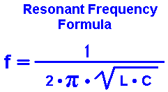
When you have a resonating loop, then you use the formula for frequency, based on values for L & C.
C1-C2 are equal, and in series. So their effective value is 1/2 of C1.
The ratio of L:C is important.
The aim is to create voltage swings which are great enough for the IC to detect. Volt levels should be within the recommended range for the IC.
Large voltage swings are associated with large L, small C.
Another factor is the amount of power coming from the antenna. If available Amperes are low, then you'll want larger L, smaller C.
Thank you very much for answers.
The datasheet says TA31136 input impedance is around 4 KOhm at 21,7 Mhz
The formula posted below is good?
The ratio of L:C is important?
Best Regards
You can use the equations in the image below. This is valid only for resistive source and resistive load.
The upper limit of L is when C2 is not required, while at low L/C ratios the circuit becomes sensitive to small component value changes.
As a general rule, L must be smaller than Lmax but not much smaller.

I do not understand, you can be a little more explicit...
The upper limit of L is when C2 is not required, while at low L/C ratios the circuit becomes sensitive to small component value changes.?
As a general rule, L must be smaller than Lmax but not much smaller.?/
Yes, that is the formula to derive resonant frequency from L & C.
It is typical for the L value to be a thousand or a million times the C value.
One factor is the amount of power going through the circuit. I suppose it might be measured in microwatts. (The sensitivity of my FM receiver is 1 uV.)
Another factor is the impedance of neighboring components.
You give the IC input impedance as 4k. You do not want this to load your LC loop too much. Therefore make your LC loop have a much lower impedance, say 1/10 of that. Then a suitable impedance for L and C might be 400 ohms.
Calculate what L value has 400 ohms impedance at 21.7 MHz.
Then calculate what C value has 400 ohms impedance at 21.7 MHz.
These only give you approximate figures. The parallelogram angles are the correct method to apply. However the L and C cancel each other's phase differences, so you should be okay.
You may not have sufficient antenna signal for a 400 ohm impedance. You may need to amplify the incoming signal.
Capacitors C1,C2 are in series or in parallel?
They are in series, since current goes through them in the same direction as the LCC loop resonates back and forth.
if you want to simulate it in a java browser
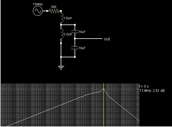
Go here , copy below and file> import text
S 0 5.0000000000000004E-8 5 50 5.0 50
% 0 1.6905175966395636E10
O 256 144 368 144 0
g 208 208 208 240 0
170 160 48 128 48 3 20.0 1000.0 5.0 0.1
l 208 48 208 96 0 1.8E-6 0.0
l 208 96 208 160 0 2.2E-6 0.0
c 256 96 256 144 0 1.0000000000000001E-11 0.0
c 256 144 256 208 0 1.0000000000000001E-11 0.0
r 208 48 160 48 0 300.0
w 208 96 256 96 0
w 208 208 256 208 0
w 208 160 208 208 0
o 2 16 0 34 5.0 9.765625E-5 0 -1 in
o 0 16 0 34 2.5 9.765625E-5 1 -1 out
- Different Input/Output matching
- How do you choose input power while doing loadpull?
- Why an input inductor required in all GPS LNA?
- Input and output impedance matching in Distributed amplifier
- In distributed amplifiers, is it total input capacitance of the gain stage or Cgs
- curve fitting for input and output matching