IIP3 to HD3 conversion
I do not have a good feeling about IIP3 - can someone give me "typical" IIP3 values for very good, medium bad as used in high end performance (oscilloscopes) or medium (RF)?
I am more used to HD3 (where I know -40dB is bad, -60dB is medium and -70 to -90 is superior).
In fact, I prefer HD3 over IIP3 because it does not allow "cheating" by just lowering the signal amplitude. What I mean is: Suppose I am interested to quantify which level of non-linearity results in which end-to-end error at system level (e.g. normalized mean squared error of a resulting signal). If I say now for a certain error level I need IIP3=x dBm I can just cheat and make it better by lowering the input signal amplitude. However, if I say I need linearity of HD3=60dB, I can not cheat because the non-linearity coefficients depend on the input amplitude. Hence
IIP3 = f(HD3,vi)
I tried to relate these two and get for example that IIP3=64.1dBm in order to get the same effect of third-order distortion for a sine wave as with HD3=-80dB at 1.24V.
Alternatively (with an amplitude 1000x smaller, i.e. 1.24mV) I get IIP3=4.1dBm.
How to I get there?
I model the non-linearity as y = c1*c + c3*x^3
From this I conclude that c3 = 4*c1/(3*Viip3^2)
Then I convert Viip3^2 to dBm assuming a resistance of 1 Ohm and a sinusoid with amplitude Viip3. Then IIP3 is given by Viip3^2/2 W which is in turn IIP3 = 10*log10(Viip3^2/2 * 1000) dBm
On the other hand, from the definition of HD3 I know that for a certain HD3, c3 must be:
c3 = 4*c1*HD3/vi^2
Equating both results and expressing IIP3 in dBm and HD3 in dB I obtain:
IIP3_dBm(HD3_dB, vi_V) = 30 - 10*log10(6) - 1/2*HD3_dB + 10*log10(vi_V^2)
While I know that HD3=-80dB is possible (although tough), does IIP3=64.1dBm for Vi=1.24V make sense (or 4.1dBm for 1.24mV)?
Thank you!
They are inversely related but dependent on output power used to make the slopes.
A rule-of-thumb that holds for many linear radio frequency amplifiers is that the 1 dB compression point falls approximately 10 dB (9.6) below the third-order intercept point.
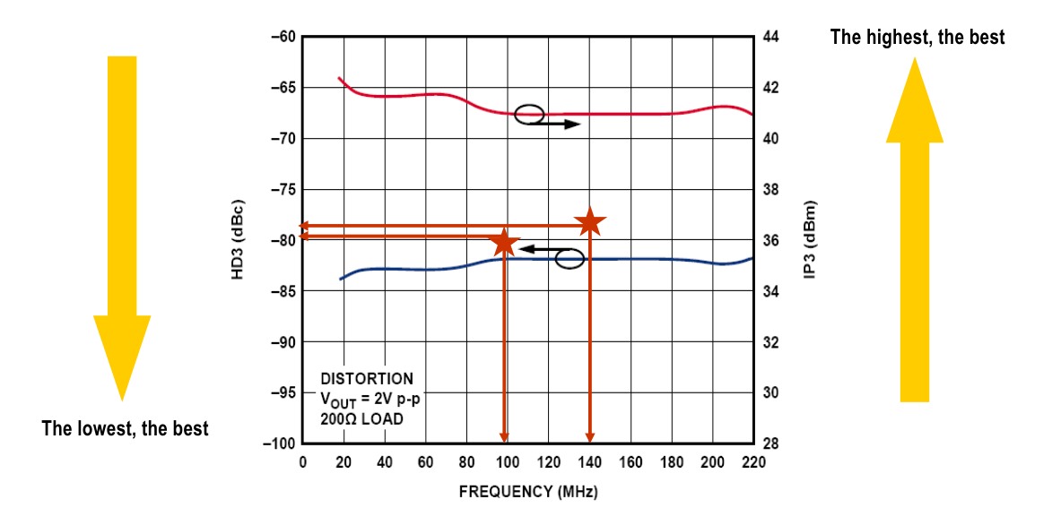
Thanks, this is a great plot! However, somehow I fail to interpret it. Does it mean that the red and blue line result in roughly the same amount of distortion? I.e., does it mean that IIP3=41dBm corresponds to roughly HD3=-82dB for 2Vpp?
This is at least not consistent with my results which would suggest IIP3=63dBm for HD3=-82dB and 1V.
Aside (if my results are correct) I propose a new FOM (IIP normalized by the signal amplitude):
FOM = IIP3 [dBm] - Vi [dBV] = 22.22dB - 0.5HD3
Unfortunately I cannot edit this post any more but in addition I have one more question:
When I have vout = c1*vin + c3*vin^3, IIP3 is defined as the voltage level at which 3rd level distortion equals first order: viip3^2 = 4/3 * c1/c3
However, most of the time, IIP3 is given in dBm. I can think now about three possible conversions:
1.) Voltage square is already power, so P = 10*log10(viiip^2) -> dBW; P = 10*log10(viiip^2 * 1000) -> dBm
2.) Supposing input voltage is amplitude of a sinusoid and assuming R=1 (as often), P = 10*log10(viiip^2/2) -> dBW; P = 10*log10(viiip^2/2 * 1000) -> dBm
3.) But why R=1? Maybe R=50? P = 10*log10(viiip^2/50) -> dBW; P = 10*log10(viiip^2/50 * 1000) -> dBm
Which one is the correct conversion? Keep in mind that I am not asking from an abstract point of view (NOT circuits/physical!), i.e., if I would just do some simulations in MATLAB where I need to generate some numbers. They can be anywhere between eps and 1/eps. So if I assume all my numbers have unit Volts and if I write vout = c1*vin + c3*vin^3 I mean Voltage-in/Voltage-out amplifier, which from the 3 options is the correct way to transform e.g. IIP3=30dBm ?
Last but not least, nearly all RF papers quote IIP3 as quality of "linearity FOM". I still cannot wrap my head around how this could be useful without specifying the input signal level at the same time. For example, http://ieeexplore.ieee.org/xpls/abs_...number=1377345 says it has an IIP3=-dBm but it does not say anything about the input signal level and it not even specifies intended application (from which an input signal level could be deducted?). How can this be useful? Is -9dBm good or bad? Comparing with the plot above it looks terrible but they still call it "highly linear". WHY?