Strange single-antenna single-rat-race coupler transceiver design, how it works?
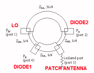
Assume rat-race have 4 ports ( https://www.microwaves101.com/encycl...-race-couplers)
Port 1 is connected to LO oscillator
Port 2 and 4 connected to Schottky diodes
Port 3 is connected to patch antenna.

This is the most strange part to me. As we know, if signal is fed to Port 1, Port 3 will be isolated port. So how this single antenna is radiating?
LO signal at port 3 is cancelled.
My guesses:
1. maybe this rat-race coupler designed to work out-of band?
2. maybe some lengths are different from standard rat-race, so PORT 3 is actually in-phase?
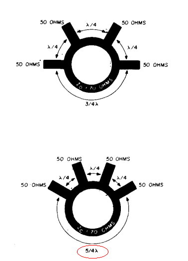
3. http://www.qsl.net/yo4hfu/Files/TG/R...96%20mixer.pdf
mayby it is not 3/4 lambda, but 5/4 lambda:

Nobody knows the answer to you question?
May I hypothesize?
It seems that antenna is not isolated port but input, LO is another input and the other two ports output sum and difference of the two input signals. It seems that way by looking at diagrams for rat-race coupler published on Wikipedia:

only symmetrically reversed with respect to vertical line.
What do you think?
Andrey, Thank for your reply!
This thing is more advanced, surprisingly i found patent describing similar design US20090015465: http://www.freepatentsonline.com/y2009/0015465.html (there also PDF with pictures of this ring)
According to this
http://www.qsl.net/va3iul/Frequency_...ultipliers.pdf
it is kind of sub-harmonic mixer and frequency doubler at the same time.
Very interesting, 5GHz LO frequency comes to port 1, and cancelled at port 3. But 10GHz harmonic is in-phase at port 3. Diodes oriented differently from standard rat-race coupler.
Read patent US20090015465 if you interested. I liked this design very much. It is half-size of traditional door opener sensor, uses cheaper oscillator transistor, and 50% smaller PCB area.
