Measuring signal strength with a TV tuner ?
Im starting to study RF with FM transmitters and I want to build a "tuned" field strength meter to test different antennas and transmitters.
I have two TV tuners: 1 analog and 1 digital (philips uv1316) which works with i2c.
I found how to use the digital one with Arduino: https://qlfecv.wordpress.com/2012/11...ica-y-arduino/
but I dont know how to measure the signal level.
Does larger signal means larger IF out or the IF have same amplitude for different signal levels ?
If its the 1st, I can measure it with 1 diode ( 1n4148 ? ) to make it DC and a capacitor ( what value? ).
Then I can read this with ADC and visualise it on a display.
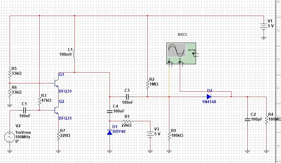
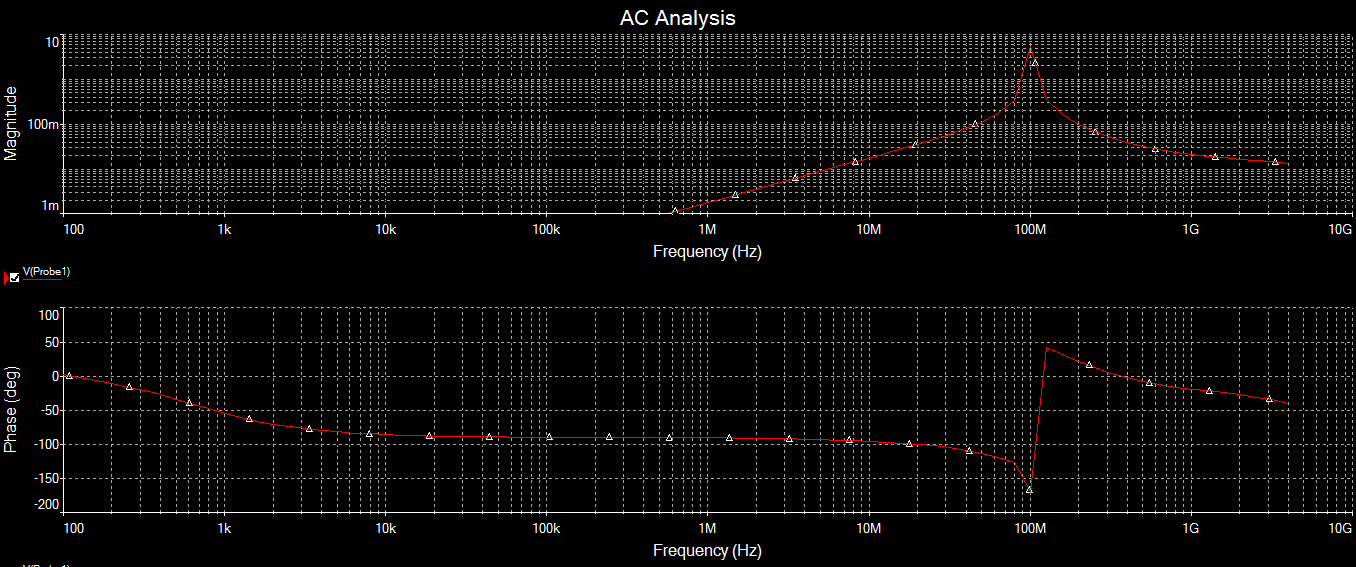
Would a circuit like this work and why it doesn't have a voltage gain ?
Is 100p for C2 good ?
You talk about FM transmitter over TV Tuner ?
Anyway..
TV Tuners "generally" have "AGC outputs" to inform the signal strength to IF amplifier in order to fix it.You can use this output to predict the signal level even the accuracy is not perfect.
Output is analog and proportional to signal strength. ( almost )
Not FM transmitter over tuner.
Im talking about:
FM transmitter -> antenna
another antenna -> TV tuner -> signal strenght measurement
I've readt that the tuner supports the FM band: "Low band - 69.25 to 154.25 Mhz"
There is a pin named AGC but my father told me that its an input and I need to set it to a fixed 2.5V-3.3V.
Or you're talking about soldering a wire somewhere on the tuner's PCB ?
--------- EDIT -----------
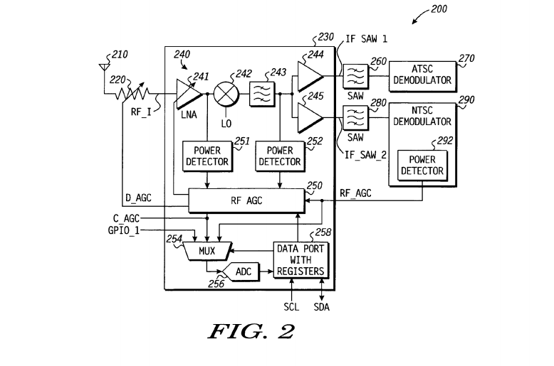
I found answer to my question: I will get the signal strength from the NTSC demodulator IC.
According to this figure, It has a power detector in it which drives the AGC in.
You're right, I confused. It was an input to adjust the RF gain..( so long time ago I used to use..)
If the signal strength is not too low, you can also use Integrated RF Detectors.
http://www.linear.com/product/LT5537
If you carefully design a circuit, you can also measure the signal strength.
Also beware of signal strength outputs of digital TV tuners. Some (maybe not all) have internal demodulators and error correction circuits, the signal strength pin isn't related to the received carrier but the BER (Bit Error Rate). They are related to some extent but several other factors can make the BER higher other than just a weak signal.
Brian.
BigBoss, very good IC but its very expensive: 30S for 5 pcs and I need to wait 1 month to arrive because I can't find it in my country, in Bulgaria.
betwix, Are you talking about a relation between the carrier amplitude and the IF out amplitude or you are talking about a relation between the carrier and the amplitude of the power detector in the NTSC demodulator after the SAW filter ?
I opened this thread because I didn't know Is there a relation between the carrier magnitude and the IF's one.
I asked that in the first post but didn't expressed myself good because my english is not perfect.
"Does larger signal means larger IF out or the IF have same amplitude for different signal levels ?"
If there is a relation: I can use an analog tuner, convert its IF to DC voltage with a diode, capacitor and measure that.
If no: I will desolder the SAW filter and the IC that controls the AGC from the TV board and use that.
About BER, I think its only about satellite tuners but Im not sure.
I know it from sat receivers.
http://www.analog.com/en/products/rf...oduct-overview
This is better.It's in stock for European customers.
https://www.digikey.bg/products/en/i...e/771?k=ad8310
http://www.mouser.bg/Semiconductors/...ad8310&FS=True
The signal strength of IF output in TV tuners is proportional to input power level except (internal/extarnal) AGC mechanism is not used only and only.But surely there is a limit.
If the Conversion Gain+IF Amplifier Gain is known, there is a possibility to extract the Input Level but it won't be accurate due to very variable Gain deviations in Mixer and LNA even IF amplifier.
So measuring a signal strength by using a conventional TV tuner is not a robust and effective way.
Your original post mentioned a digital tuner. What I envisaged was a tuner with digital output as are used in terrestrial and satellite TV in most countries these days but I think you were meaning an analog tuner with digital tuning control which is quite different. A true digital tuner provides a serial data stream at it's output and measures signal strength by detected errors rather than by how strong the received signal is. They are related, a weak signal is likely to produce more errors but a strong signal can still have a high error count under certain propagation conditions, for example when short delay reflections are present.
There is an interesting experiment to try, these two methods should give the same results:
1. use the X-axis output of an oscilloscope (if it has one) as the tuning voltage source and monitor the tuner output on one of the Y channels. Use a slow sweep rate, no more than about 100mS/Div.
2. generate a ramp signal, feed it to the X-input of an oscilloscope and the tuning voltage input simultaneously and monitor the output on the Y channel.
What you get is a crude spectrum analyzer showing all the signals present in the frequency range of the tuner.
Brian.
BigBoss, this is IC is very expensive too.
betwix, interesting experiment, I will try for sure. Thanks for the idea!
I didn't know that there are tuners with digital IF out.
I am talking about tuners with digital tuning.
My progress as follows:
I cut the TV board where is the IF amplifier/NTSC demodulator IC and soldered the tuner back.
Then I disconnected the AGC mechanism and connected the tuner to fixed AGC with trimmer setted to 3V
I connected a potentiometer to sweep the varicap voltage by hand with external +30V, connected +12V to the LOW VHF pin and the supply pin.
And measured 9.8V at the AGC output of the IC. I thought that this voltage will change according to the input level but nothing happens when I sweep the potentiometer.
It stays 9.8
Lately I found that this tuner has a pin named AFC (automatic frequency control) which I was left floating in the first experiment.
Then I connected it to a voltage divider with 2.2k to ground and 2.2k to +12V and tried again.
The result is the same: rock solid 9.8V
Another lately: my father told me that this pin is actually an output and I thought that I can get the signal strength from there but I had no success because this pin sweeps with the potentiometer.

I found a way:
I attached the AGC mechanism back and measured the AGC voltage while sweeping the frequency.
Normally its 9.7V and it goes to 3-4V when it get tuned to my transmitter.
I leaved it tuned, disconnected the transmitter supply and it goes to 9.7V again.
Can I make a spectrum analyser with 50hz sawtooth sweep or this is too fast ?
Because I have an old TV and I can connect the varicap input to the vertical deflection coil 50hz sawtooth pulses.
Then I can show the result via the horizontal coil using a transistor to drive it.
No I can't. I tried and It doesn't worked.
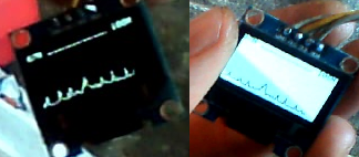
However I succeeded to make one with MCU and a tiny OLED display.
I will post photo later when I get my grandmother's mobile phone to make one.
Im using old Nokia 6300, the camera is not good, its usb is the old standart and I dont know where are my old USB cables..
Im using the digital tuner as DAC since it have pin that outputs the internal varicap voltage. I connected this output to the varicap input of the analog tuner soldered on the TV board with the IF amplifier IC and the AGC mechanism. As I mentioned: the agc voltage goes 3-4V with strong signal and 9-10V without a signal. I got this voltage, scaled it to 0-5V and fed it to the ADC of the MCU.
MCU --i2c-> DIGITAL TUNER used as DAC --> ANALOG TUNER + IF amplifier IC that controls the AGC --agc-voltage-> scale circuit -> MCU's ADC
The scan speed is not fast but its good enough and Im pretty happy. I think that the display slows it and must try to make it with "TV out" instead the display.
If its slow again -> I will make a low freq triangle wave generator to drive the horizontal/vertical deflection of a TV and the varicap voltage of the analog tuner.
Some code:
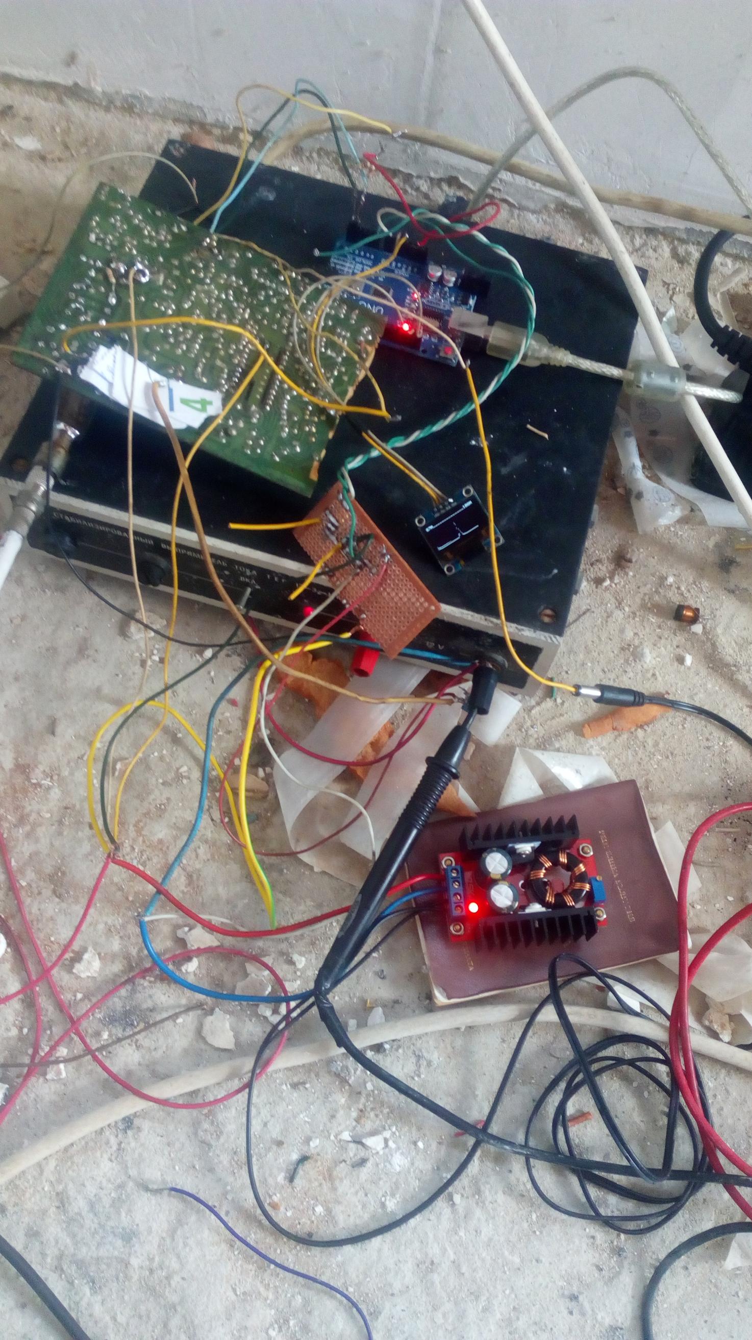
Here are the spectrum analyser, my transmitter, my dog and my LC meter.
The display is very tiny and I 'll try with TV out or the TFT display I have.
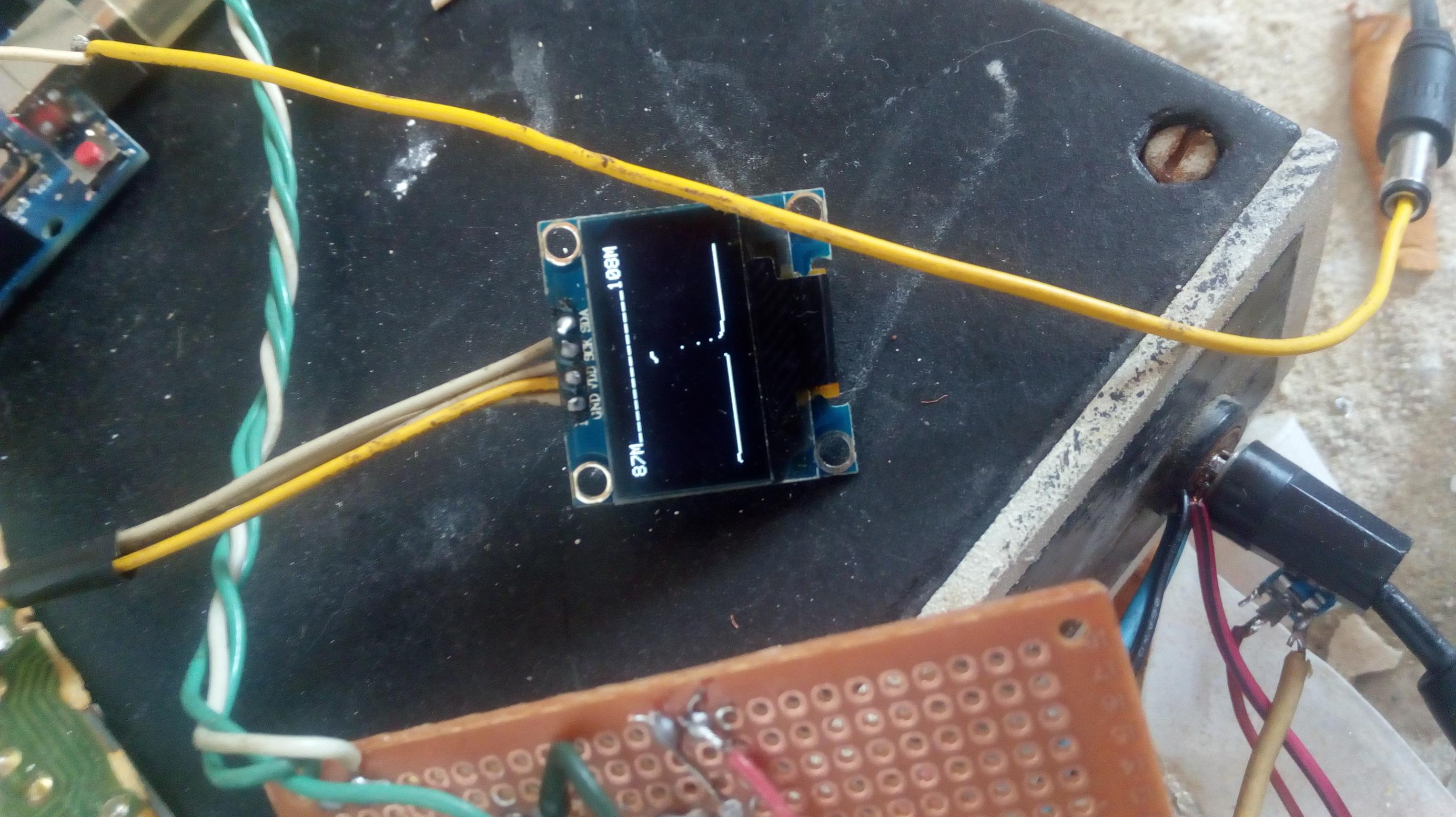
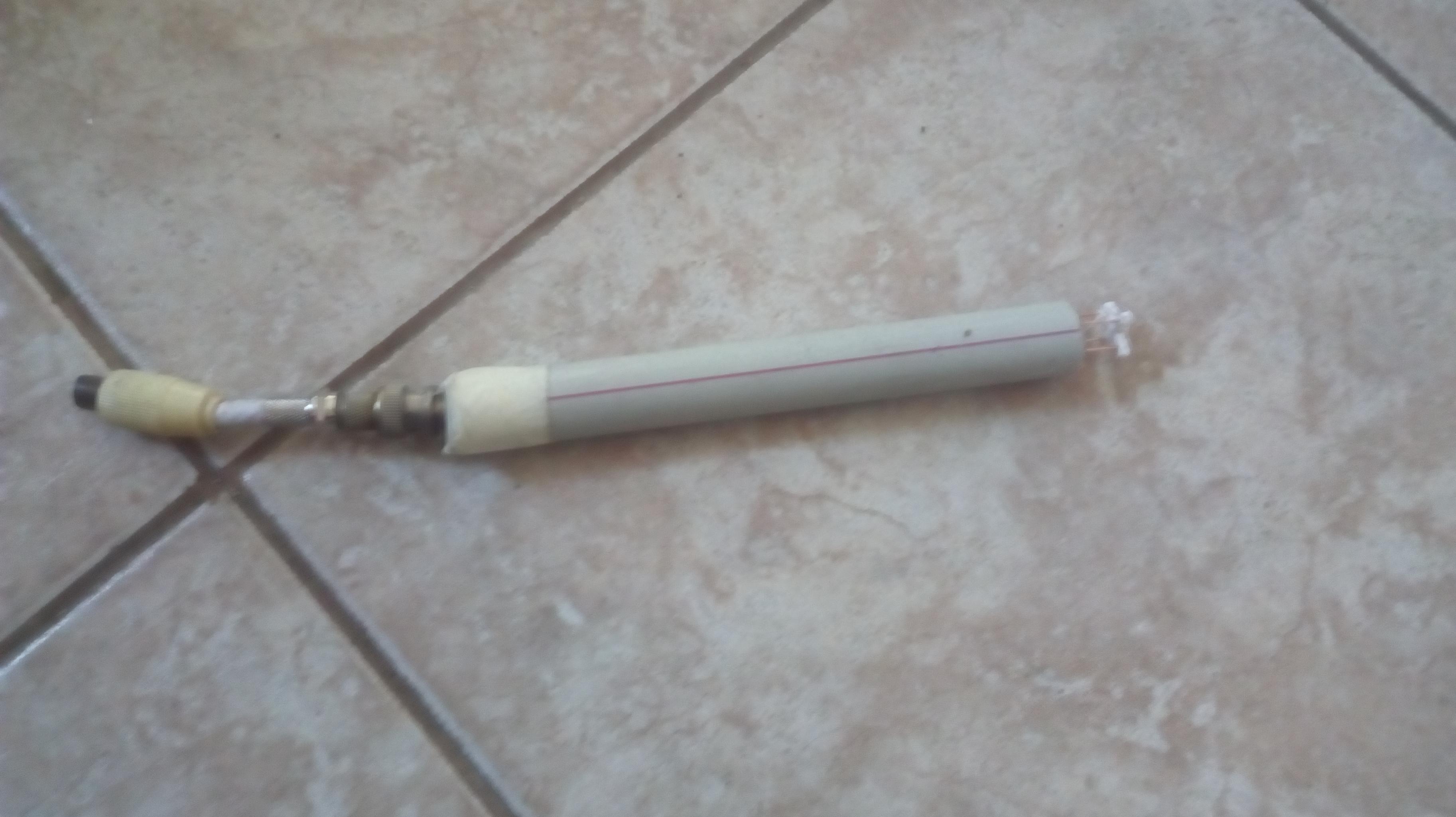
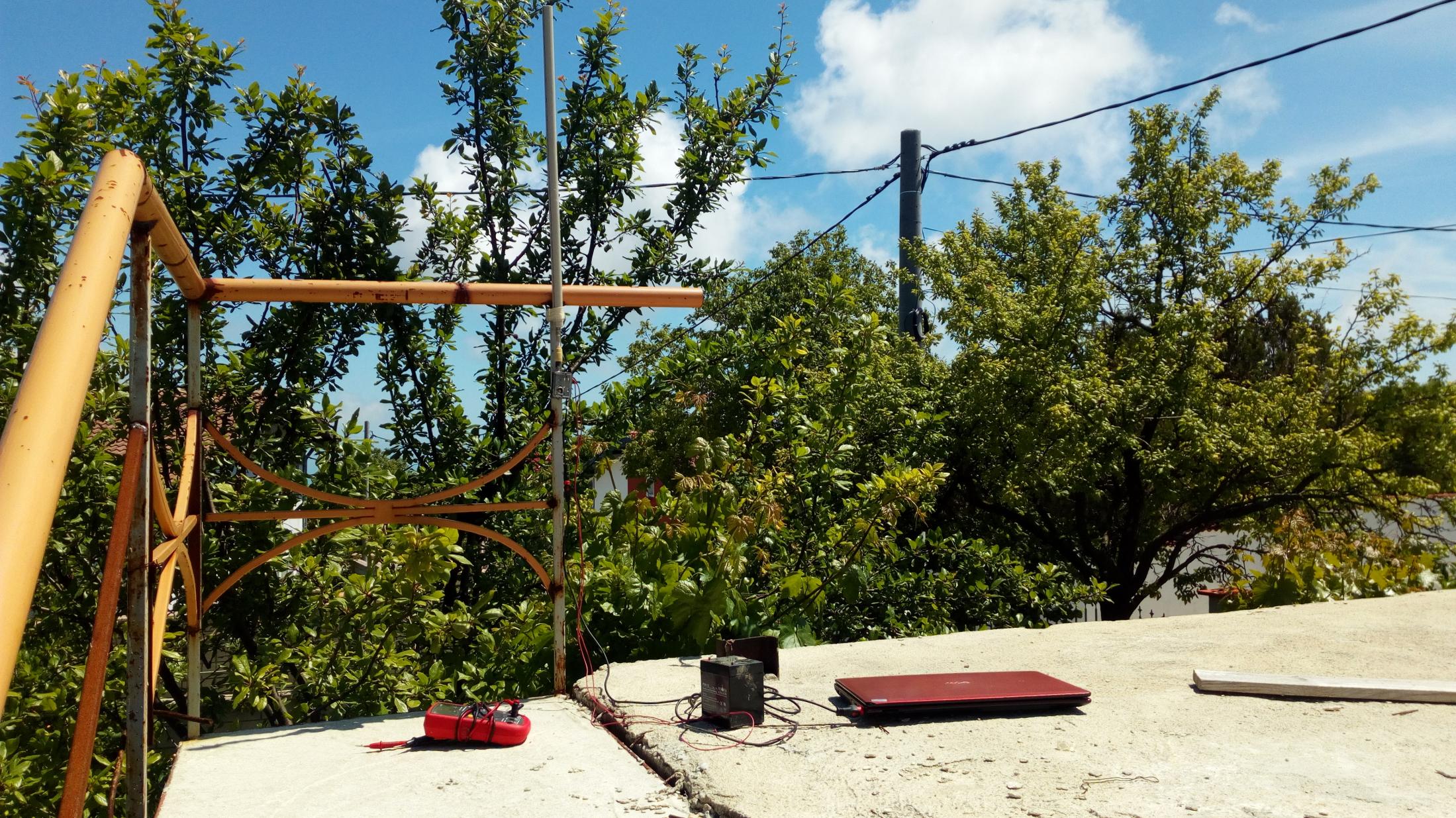
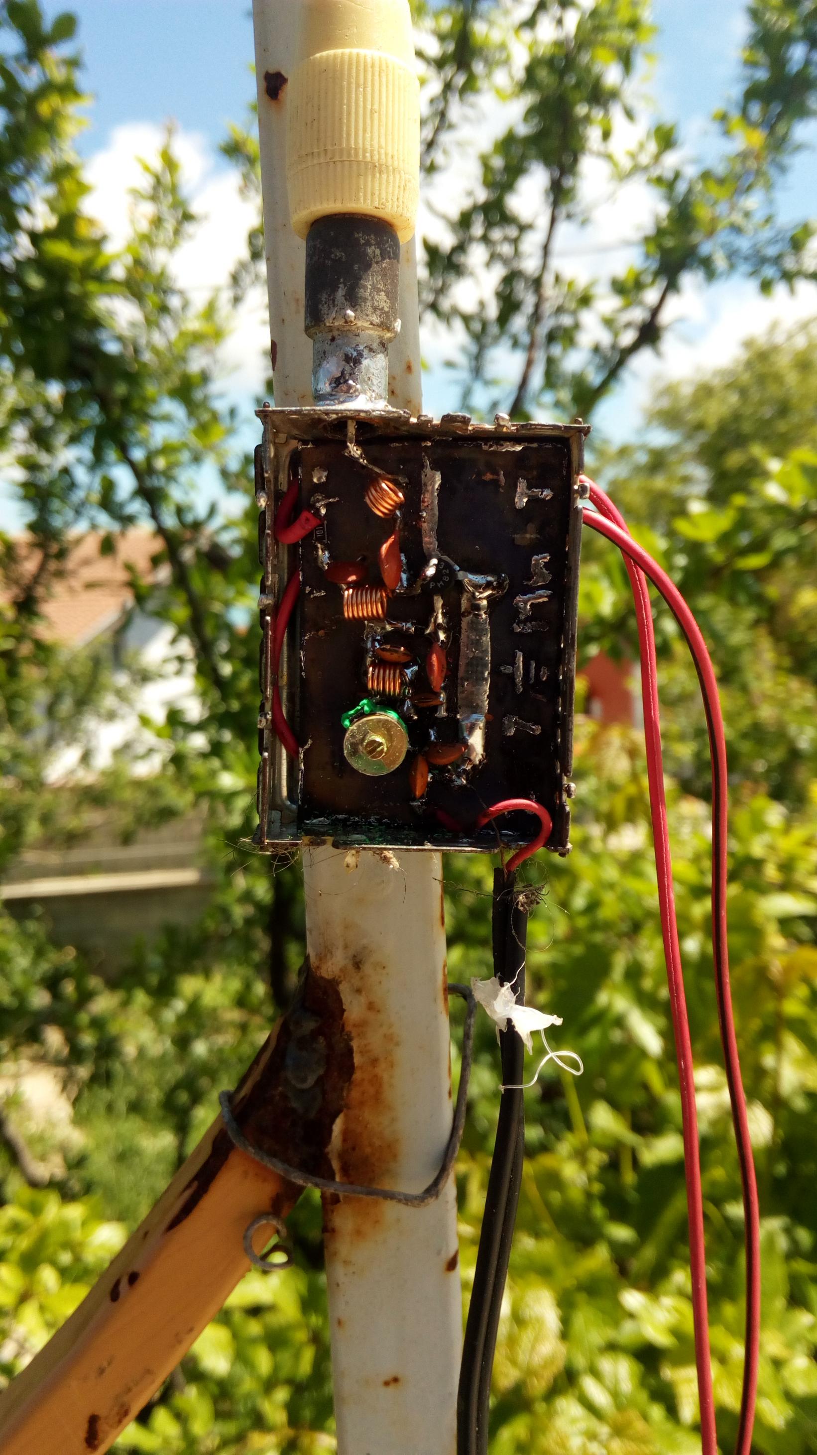

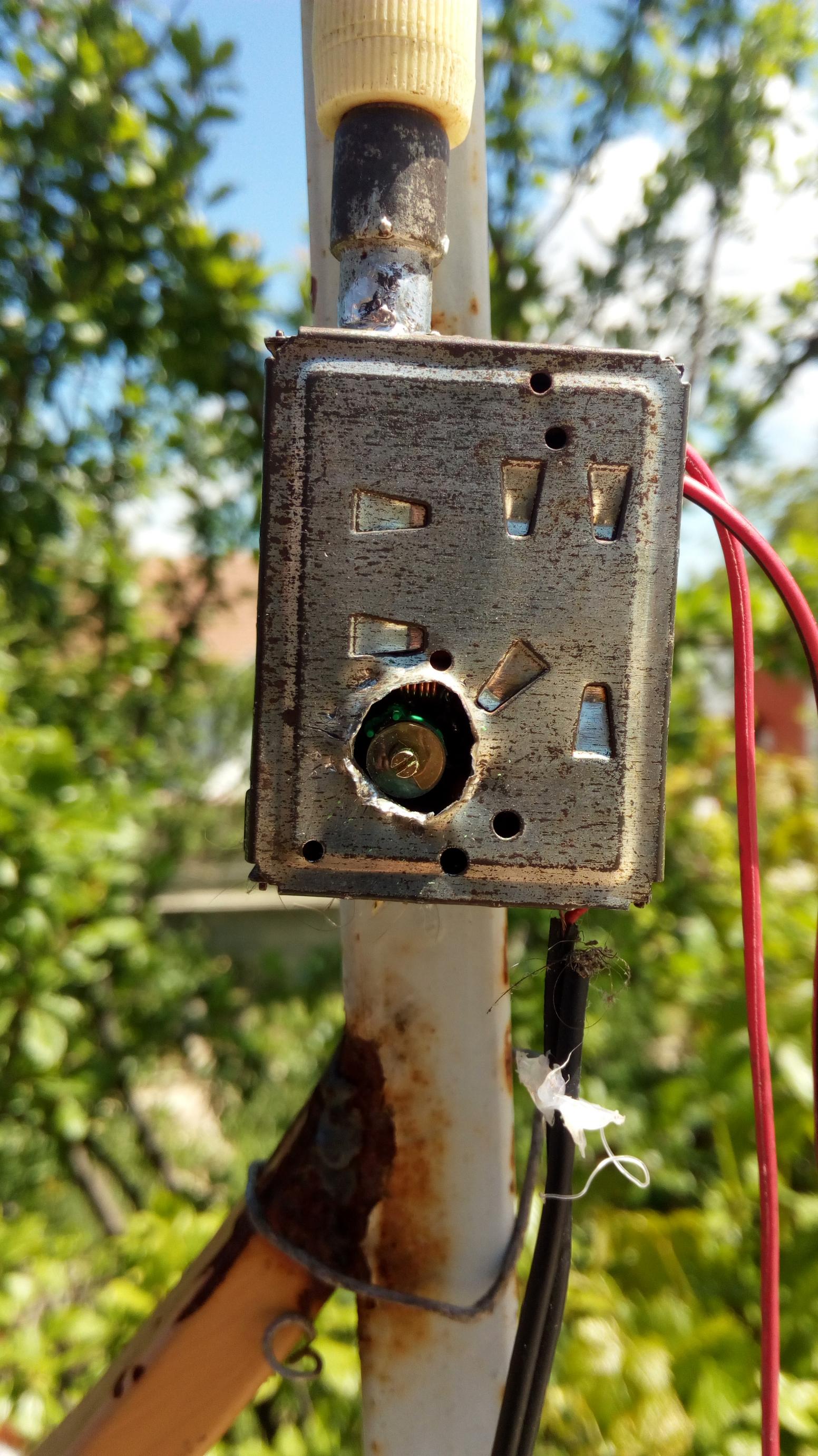
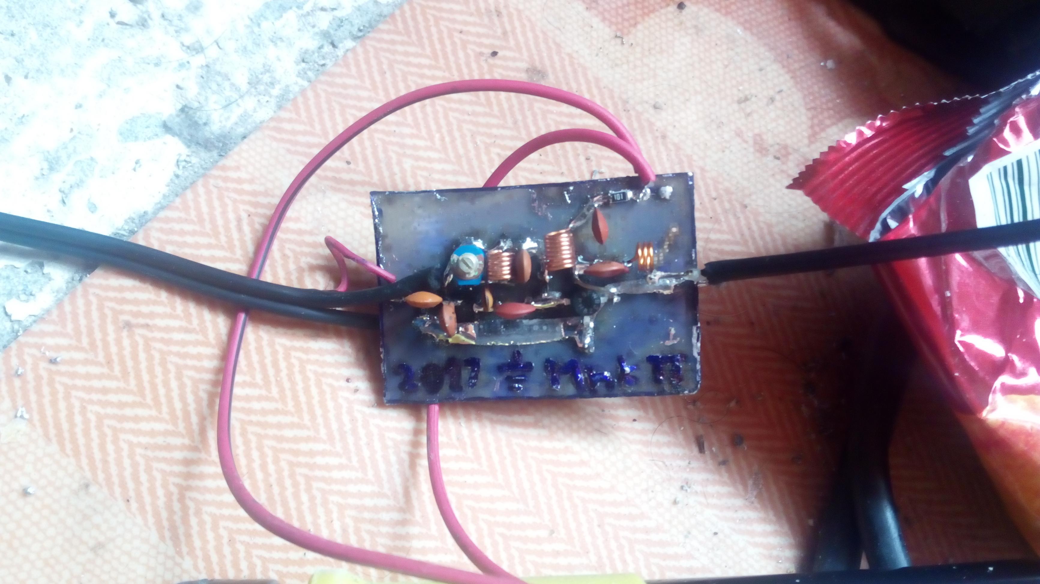
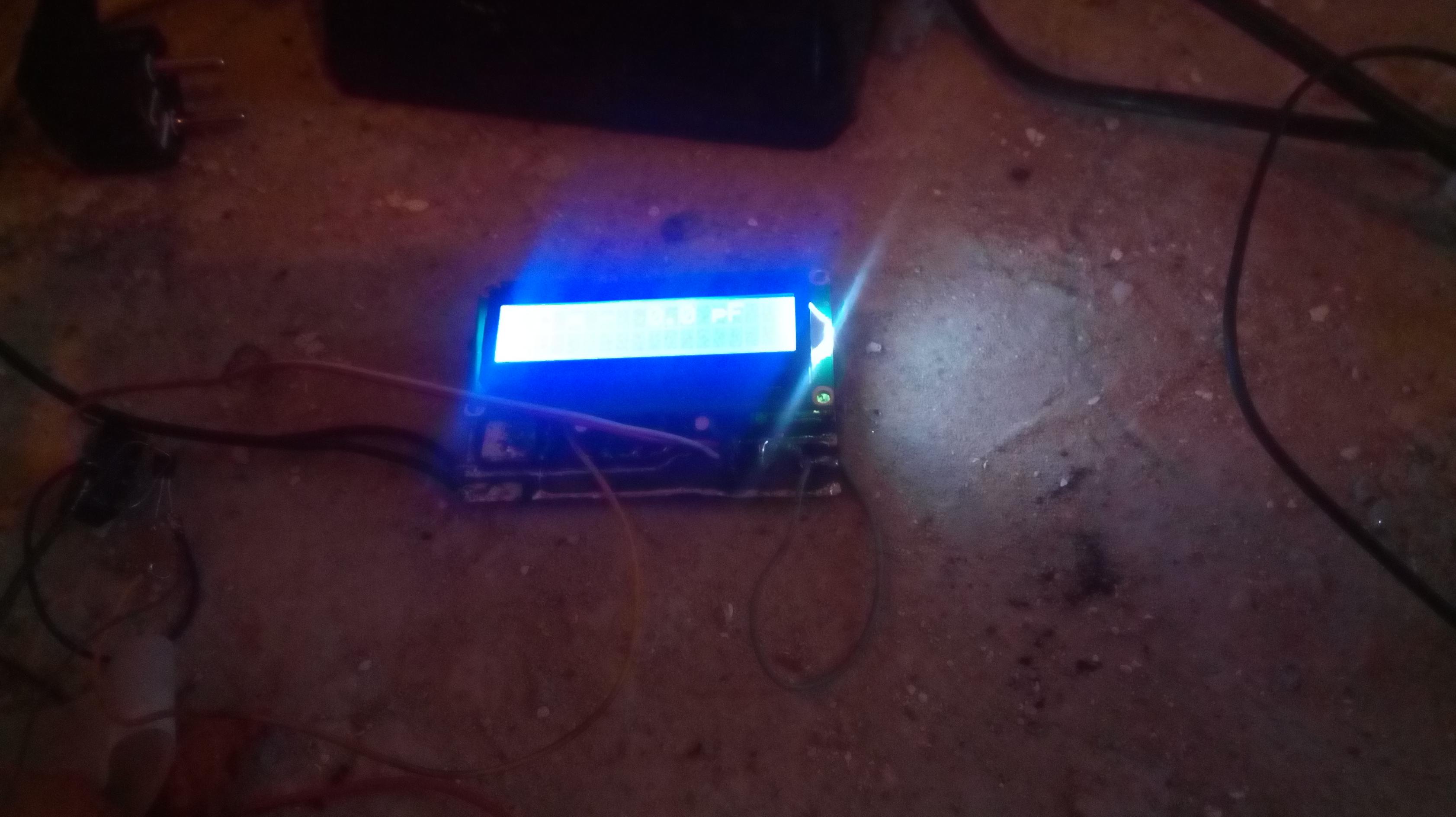

Look at my new spectrum analyser for the FM band, using the TEA5767 chip.
/* * * * * * * * *
  RF Electronics
  Spectrum Scanner

  v.0.0.5
 * * * * * * * * */

#include <SPI.h>
#include <Wire.h>
#include <Adafruit_GFX.h>
#include <Adafruit_SSD1306.h>

//#include "rfe.h" // rfe logo


#define OLED_RESET 4
Adafruit_SSD1306 display(OLED_RESET);

#if (SSD1306_LCDHEIGHT != 64)
#error("Height incorrect, please fix Adafruit_SSD1306.h!");
#endif

/****
***/

int dw;
const float pi = 6.047619047619048;

byte buffer[5];
byte signal;

byte firstRun = 1;
byte prev[2];

bool disp = false;

/***
****/

void setup()
{
  // Display init
  display.begin(SSD1306_SWITCHCAPVCC, 0x3C); //0x3D too

  // Clear the buffer.
  display.clearDisplay();

  // draw the logo
  /*
  display.invertDisplay(true);
  display.drawBitmap(0, 0,  rfe, 128, 64, 1);
  display.display();
  delay(2000);
  display.invertDisplay(false);
  display.clearDisplay();
  */

  //loading_animation();

  display.setTextSize(1);
  display.setTextColor(WHITE);

  dw = display.width();

  TEA_init();
}

void loop()
{
  display.setCursor(0,0);
  display.println("87M ____________ 108M");

  for(int i=0; i<dw; i++)
  {

    //radio.selectFrequency( round((float)i/pi * 10) / 10.0 + 87.00 ); // pi = (dw-1)/(108-87)
    //radio.selectFrequency( round_to_dp((float)i/pi, 2) + 87.00 ); // pi = (dw-1)/(108-87)
    //radio.selectFrequency( i/6 + 87 );
    //setFrequency( (float)(i/6 + 87) );
    //setFrequency( round_to_dp((float)i/pi, 2) + 87.00 );
    setFrequency( round((float)i/pi * 10) / 10.0 + 87.00 );


    Wire.requestFrom(0x60,5); //reading TEA5767
    while(!Wire.available()) ;
    for (int i=0; i<5; i++)
      buffer[i]= Wire.read();
    signal = buffer[3];


    //display.drawPixel(i, 62-radio.getPowerLevel()/5, WHITE);
    if(firstRun)
    {
      display.drawPixel(i, 63-signal/13, WHITE);
      firstRun = 0;
    }
    else
      display.drawLine(prev[0], prev[1], i, 63-signal/13, WHITE);
    prev[0] = i;
    prev[1] = 63-signal/13;

    display.display();

  }

  prev[0] = 0;
  prev[1] = 63;
  firstRun = 1;
  display.invertDisplay(disp);
    if(disp) disp=false;
    else disp=true;

  display.clearDisplay();
}

void setFrequency(float frequency)
{
  unsigned int frequencyB;
  unsigned char frequencyH=0;
  unsigned char frequencyL=0;

  frequencyB = 4 * (frequency * 1000000 + 225000) / 32768;
  frequencyH = frequencyB >> 8;
  frequencyL = frequencyB & 0XFF;
  //delay(100);
  Wire.beginTransmission(0x60);
  Wire.write(frequencyH);
  Wire.write(frequencyL);
  Wire.write(0xB0);
  Wire.write(0x10);
  Wire.write((byte)0x00);
  Wire.endTransmission();
  //delay(100);
}

void TEA_init()
{
  unsigned int frequencyB;
  unsigned char frequencyH=0;
  unsigned char frequencyL=0;
  float frequency=87.5;

  frequencyB=4*(frequency*1000000+225000)/32768; //calculating PLL word
  frequencyH=frequencyB>>8;
  frequencyL=frequencyB&0XFF;

  delay(100);

  TWBR = (F_CPU/400000L - 16)/2;
  Wire.beginTransmission(0x60);   //writing TEA5767

  Wire.write(frequencyH);
  Wire.write(frequencyL);
  Wire.write(0xB0);
  Wire.write(0x10);
  Wire.write(0x00);

  Wire.endTransmission();

  delay(100);
}

float round_to_dp( float in_value, int decimal_place )
{float multiplier = (float)pow( 10.0f, decimal_place );in_value = ((float)round( in_value * multiplier )) / multiplier;return in_value;
}
