FSK Modulator Hardware
I have to design RF frontend transmitter.
Features of the transmitter will be;
10 Channels
fo=2.46 GHz
Power = 1 to 10W / 8 steps
Modulation = FSK
Data Baudrate = 1 Mbits
Voltage = 28V
I have a couple of questions.
Firstly, how channels are calculated ? Does it depends on my PLL quality ? So If I can produce (2.46Ghz - 2kHz and 2.46Ghz + 2kHz) and (2.46Ghz - 4kHz and 2.46Ghz + 4kHz) , does this mean I have two channels ?
Secondly, which way is better, using a IC for this purpose or designing a new system ?
Can I use two PLL circuit and RF switch for FSK modulation ?
In brief, can you guide me, so I can work on it.
The term "channel" related to RF transmitters is ambiguous. With small radio devices (SRD), it usually refers to assigned fixed bands within the frequency range covered by the transmitter. A reasonable channel width depends on the achievable frequency stability and the signal bandwidth. In case of FSK with 1Mbps signal rate, a channel width below MHz range makes no sense.
As another point, a FSK transmitter with several watts power in the 2.4 GHz band will conflict with RF regulations, I guess also in your country.
Thanks for answer,
I am not going to do it in real life. However, I must design it.
My first thought is to use two ADF4355-2 and generate a signal in the 2.4Ghz band then using RF switch, switching between them according to binary data to create FSK modulation.
Basically the system is like below :
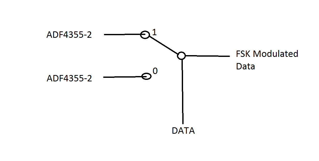
However, I am not sure, If this can be used as a FSK modulator.
That's a bad idea, because it involves undefined phase steps during switchover, involving huge out-of-band interferences. FSK is usually designed to generated continuous phase, only changing instantaneous frequency.
A simple way to generate FSK at high rates with a PLL synthesizer is to inject the modulation between loop filter output and VCO input. Dedicated transmitter PLLs are usually injecting the modulation in the fractional frequency divider.
Thanks a lot,
Still I didn't understand why we need 1MHz bandwidth for 1Mbit buad rate ?
For example my data rate is 10Mbit/sec , Fc = 2400MHz , and deviation frequency is 10 kHz . So my PLL swings between 2.4GHz-10kHz and 2.4Ghz+10kHz at the speed of 10MHz ? Why I need 10MHz bandwidth
Read about relation of channel capacity, bandwidth and modulation method, e.g. https://en.wikipedia.org/wiki/Shanno...artley_theorem
I didn't attempt to calculate the required channel bandwidth exactly, just wanted to mention the order of magnitude. You'll review literature for detailed considerations. Binary FSK is a simple but not particularly bandwidth effective modulation method.
Thanks for help,
As I understood from the new sources, minimum bandwidth is
B = 2 * (delta(f) + fb)
B = Minimum Nyquist Bandwidth
delta(f) = frequency deviation |f(mark) - f(space)| (Hertz)
fb = input bit rate
so If I choose frequency deviation as a 250 kHz then my minimum bandwidth is 2.5 MHz , right ? . However some sources say Bandwidth = fb + 2 * delta(f)
Then if I choose frequency deviation number lower, my minimum bandwidth gets narrower. So why shouldn't I choose it minimum ? I keep reading about this issue.
From another source I read that bandwidth effiency is defined as the troughput data bit rate : Rb in bits per second, to the required frequency bandwidth occupied by the modulated RF signal BT (hertz)
So my bandwidth effiency is : 1,000,000(bits/sec) / 2,500,000(Hz) = 0.4 bits/second * Hz ?
My last question is , if my baudrate is 1Mbit/sec , then my PLL must lock under 1us right ?
No, PLL is expected to stay locked.
Then I must change input of VCO or reference clock ? And in all of these time PLL lock doesn't break ?
As mentioned in post #4, there are two usual ways to generate FSK with a PLL synthesizer
- switch the frequency divider
- feed a modulation above loop bandwidth to the VCO
In both cases, the PLL should stay locked. Modulating the reference frequency input would be another possibility.