4.5 GHz VCO in ADS Simulator
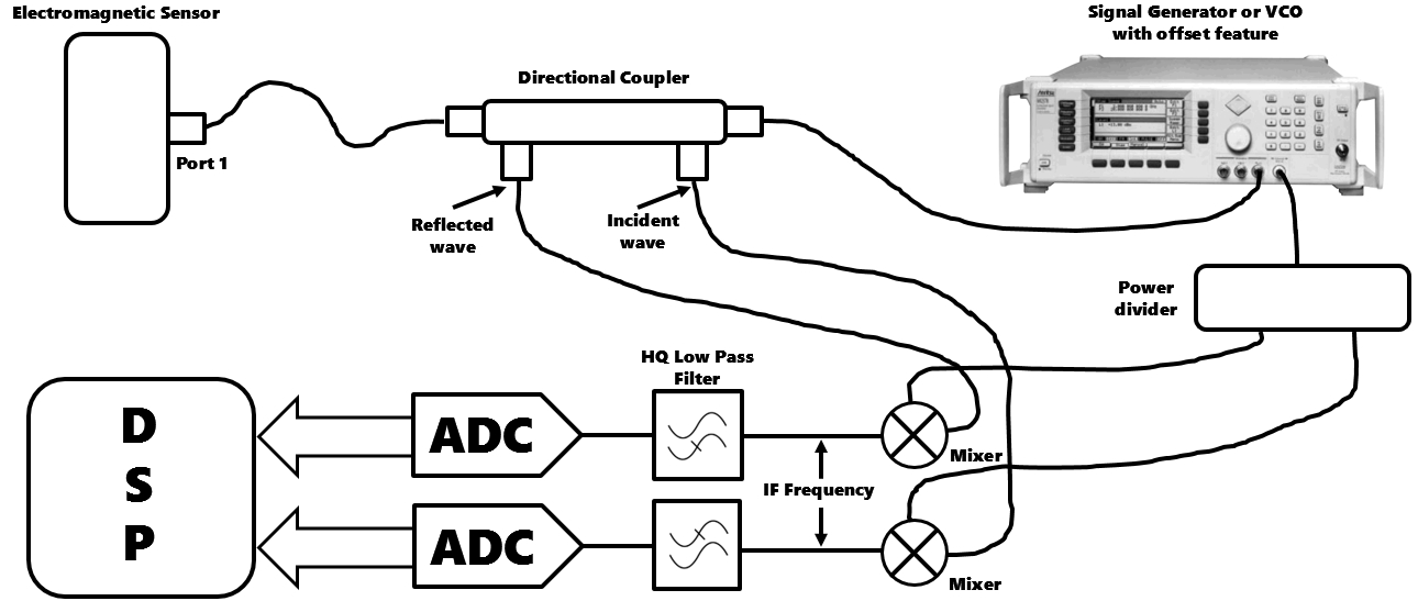
I have to make a system to detect magnitude of frequency from an RF one-port sensor/resonator (resonating at 4.5 GHz).
I wanted to first analyze the system on ADS tool. I have to make a VCO in ADS which should generate a 4.5 GHz frequency, may be it should tune from 4.3 GHz to 5.4 GHz. And, it should also have an offset feature.
I am very new to ADS tool. I have started learning it since yesterday.
Though, they have VCO in ADS, I tried to put it in my circuit but it is not working. I do not know what is the reason.
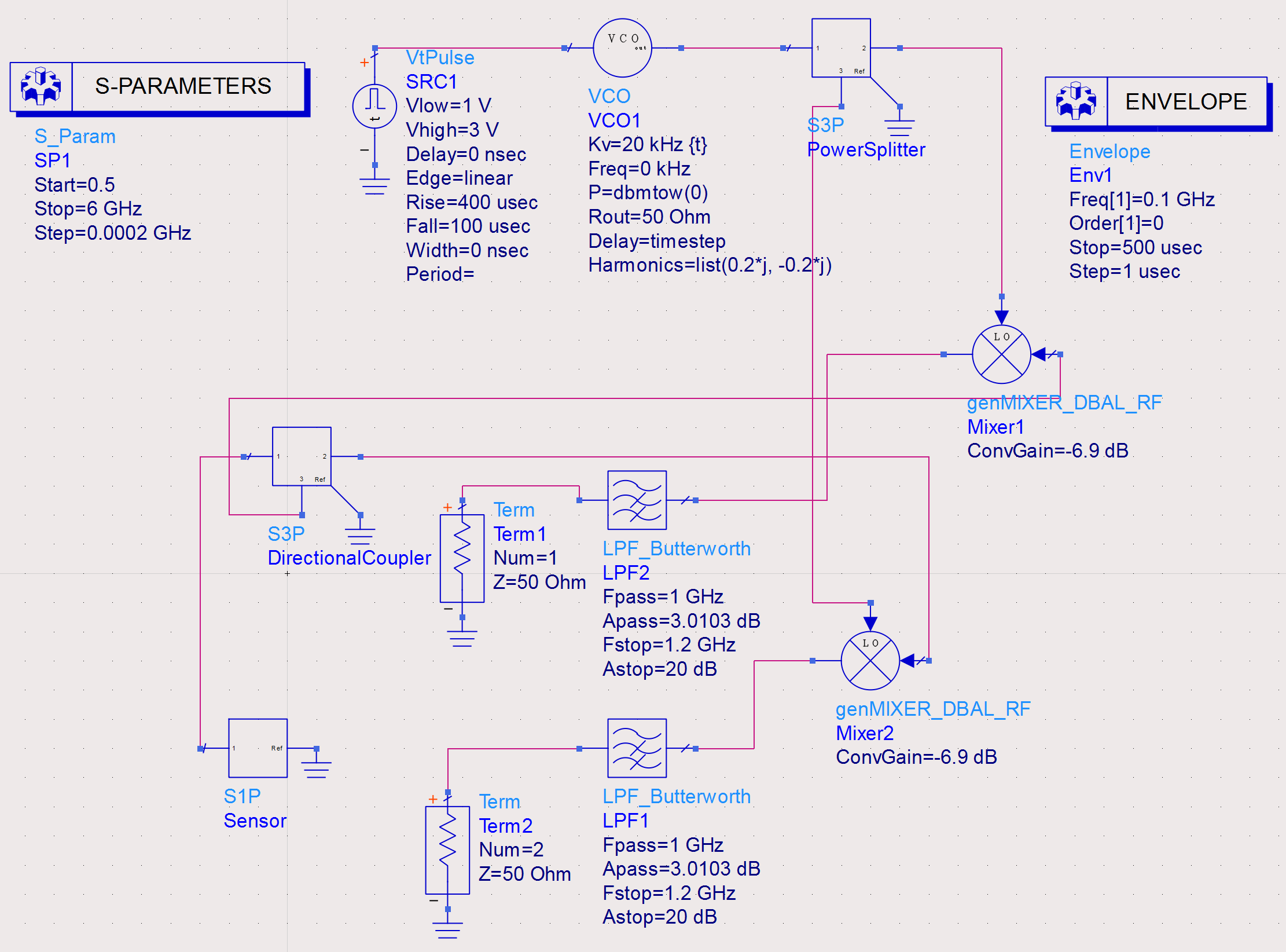
The snapshot of the ADS circuit is attached here. The signal from VCO is not going to Power Splitter.
Please see the images. I am trying a lot to search find the problem.
Would be great if anyone can help solve this issue.
Thanks!
Pictures:
1.Schematic Diagram of the Proposed Frequency Detection System
2. Entire system in ADS simulator till LPF. (after LPF the DSP kit will come into play, later on)
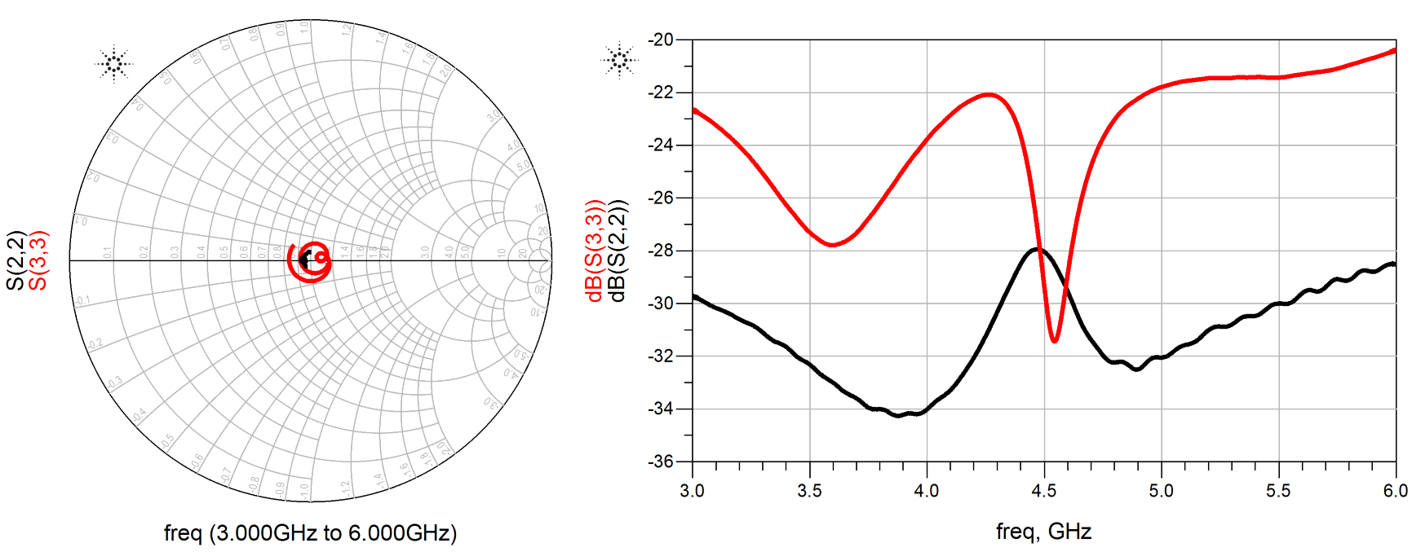
3. S-parameter output at mixer terminals (showing that VCO is not working)
4. VCO part (connected to power splitter)


There are many mistakes in your set-up.
Why VCO freq. 0Hz ?
Why pulse voltage source for ? Sweeping Vtune ? It's completely bad idea..
Why envelope simulation ? Is there any modulation or something ? HB is enough to see the wanted spectrum.
I suggest you read ADS workshop literature and simulation techniques on the internet and study some basics to complex circuit simulation then try to simulate this project.
Otherwise you will confuse more..
Thanks for replying.
Let me search the literature and I will definitely try to correct my mistakes.
I will update it and check results.
I am able to correct the VCO part and I am getting this response. This is output of Vout data, the s-parameters at mixers and the updated ADS circuit is attached with this reply. I am also attaching the s_11 of my resonator which has to be measured.
Snapshots are attached.
Can you please verify if the circuit is working well.
