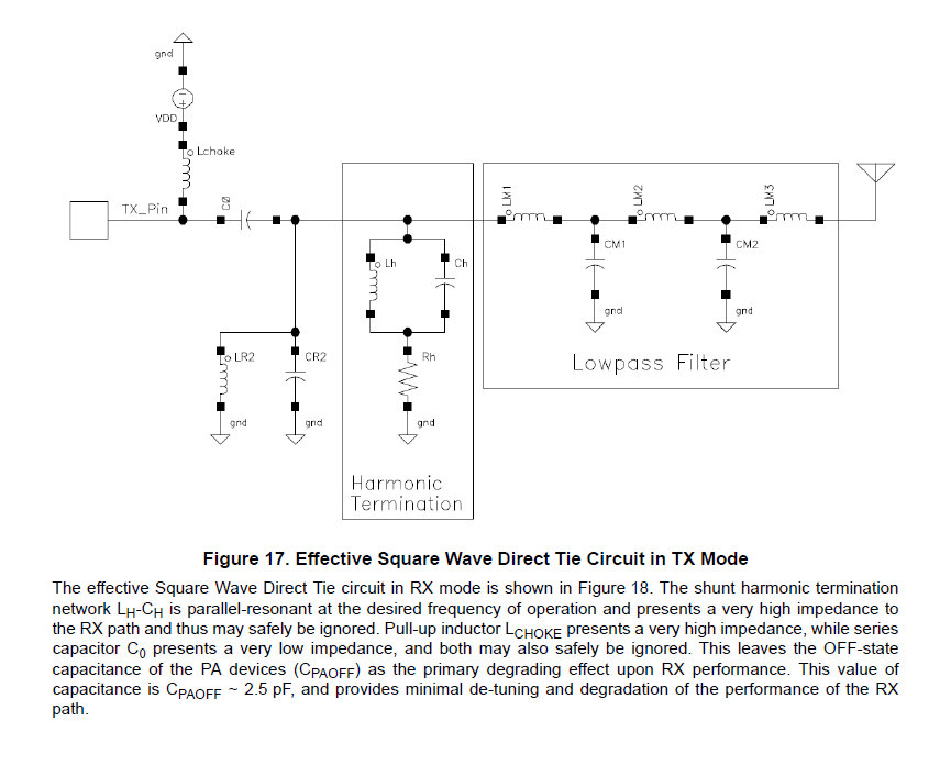
What is the output impedance of a square wave switch-mode RF "amplifier"?
时间:04-04
整理:3721RD
点击:

I am trying to get an idea of what the output impedance of this circuit would be. First off, the harmonic termination is terminated with a 50 Ohm resistor (Rh) Lh and Ch are parallel resonant at the output frequency.
LPF Characteristic impedance would be 50 ohms.
My theory is that Rh would dominate as the impedance of the system and be less dependent on the switch characteristics, however, my other theory is that is mainly depends on the switching current from the Lchoke back EMF. I also know that the voltage at Lh/Ch resonance can be much greater than VDD which makes me think it's mostly dependent on Rh.
Can anyone shed light on this and help me understand what the impedance of a system like this would be?
The picture of the example was taken from the Si446x application note AN648 and is figure 17.
if it is an efficient source of power into that antenna, the output impedance of the switch mode amplifier therefore has to be 50 ohms, or whatever the antenna impedance it is tuned to work with is.
An ideal square wave generator, respectively switch with ideal choke has zero output impedance and can source any power according to it's output voltage and load impedance.
Matching a real class F PA deals of course with finite switch impedance and other parasitic elements.
I wouldn't assume this. Could be either a current or voltage square wave, either an open or short circuit equivalent.
