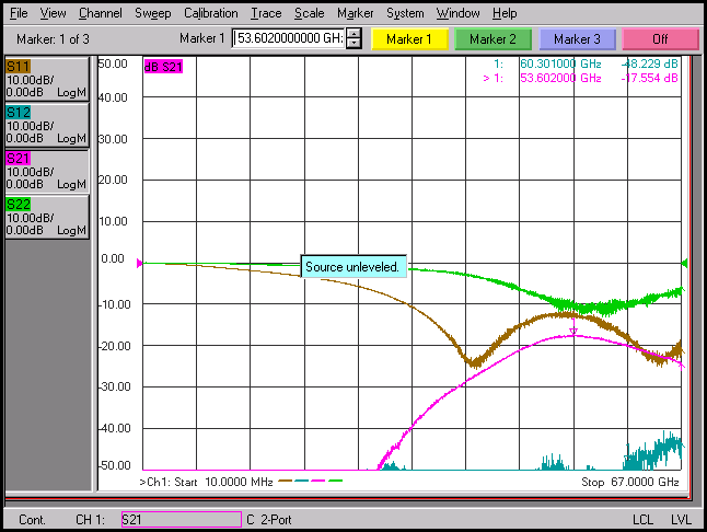
LNA measurement scattering parameter
recently i have measured my mw-lna but i think that something is wrong with the output S parameters. i put the output results. do you think S parameters are normal? does amplification happen? is the LNA stable? or its a normal failed LNA? can you find the problem by just looking at the S parameters?
many thanks

S11, S22, and S12 are fine. The LNA should be stable based on those parameters.
The only problem is negative S21, which means your LNA has no gain.
But because the shape of the S21 looks ok, I would assume that your transistor model has an issue.
Thanks a lot for your reply but i should mention that this is measurement and not simulation. the circuit is fabricated in 28nm TSMC technology and S parameters are real measurements. so do you think the measurement may have problem and not the circuit? Do you think the calibration of RF-spectrum analyzer which is used for measurement is not accurate? I have doubt about the validity of the S-parameters since all of them are below zero and S21 is lower than S11 and S22. shouldn't at least one of S21 or S12 be above zero? or shouldn't at least S21 be more than S22 or S11? Do you think the measurement can be believable and its a simple fail fabricated LNA? thanks
I think that is a biasing problem.Because as said, S11 and S22 "seem" fine but there is not gain due to very low gm.
Check the bias voltages and currents.If they are normal, the problem is more complicated.
thanks a lot for your reply.
The bias voltage is 1V and the current is 19mA and its close to what i had simulated or in the other word bias measurement is close to simulation.
In measurement, was the VNA source power small enough?
Yes. we checked for all input power range. from small to 15dm but for all of them, S21 was similar. it didn't matter the input was 1dbm or 15dbm, S21 was same.
?. May be there's a misunderstanding of scalar db S-parameter representation. In my understanding, 0 dB S11 and S22 are showing open or short circuit, they don't seem to indicate that an amplifier is connect at all. Good matching would show as low (ideally -infinity) dB number.
Indeed.
Hhmmm ... no saturation of LNA? I see "source unleveled" warning in your VNA screenshot, so maybe your level wasn't set as you expected.
Otherwise, I would suspect that something is wrong in the LNA input, and power doesn't get to the transistor. But S11 of -10dB doesn't look that bad.
I don't know what you get for LNA S21 if they are unstable and oscillating at some other frequency. Did you check with a spectrum analyzer if there's any oscillation with the port terminated into 50 Ohm (like VNA measurement)?
Can you show how the input and output ports are coupled?
I think the ports should be OK since S22 and S11 are acceptable
S11 and S22 would be only plausible if input and output coupling is made with x GHz cut-off bias T, e.g. fF capacitors or very low inductance. Is it so?
Even then, the perfect reflection factor below 20 GHz looks suspicious.
Actually I don't see perfect reflection (input or output) below 20GHz.
Anyway, as I already mentioned, your S11, S22, and S12 looks fine. Maybe S12 (isolation) is too good to be true at this microwaves frequencies, and following this information may give you a hint why S21 (gain) is negative.
The band-pass shape of S21 shows that you might use a high-pass input matching and a low-pass output matching networks.
Not to the last, check if your active component is still alive, even you get some collector/drain DC current.
Would be good if you can post your schematic.
S11 and S22 starting from 50 GHz, seems ok to me (I don't know your frequency range). What about input and output matching networks losses ?
You said that you tested it form 1 dBm up to 15 dBm, but the gain didn't change. This means it's not saturating: but are you very sure S21 is not changing from 1 to 15 dBm input power ?
I think you should try with a lower input power. Let's say -20 dBm. From simulation which gain and OP1dB is expected ?
If the device is not saturating with 15 dBm input power (considering the bias point of only 1V 19 mA) in my opinion the device could be broken (as suspected by vfone) even if in this case S11 and/or S22 should be worse or the iput signal is strongly attenuated before reaching the gate of the transistor. Both these causes also can explain the very good S12.
Furthermore as already noticed, the instrument is giving the error message "output unleveled". Possibly is related to the very wide span you set (10 MHz to 67 GHz). You could try to set the span from 40 GHz to 67 GHz. In any case if the message is still present the S21 measurment couldn't be 100% reliable.
Did you notice the post that it is asked to check the output with a spectrum analyzer? In amplifier testing, "source unleveled" message appears mostly in case of something unstable at the output. First, you have to make sure your amplifier does NOT oscillate using a spectrum analyzer. Do not forget to set reference level to maximum or use an appropriate attenuator(20 dB typ.) before connecting to spectrum analyzer.
1 dBm, 15 dBm... too high levels to test an LNA, even the equipment may be damaged.
Getting help from someone who is experienced in equipment use and testing may be a good idea to proceed.
measurement LNA parameter 相关文章:
