Assumptions about magnetic feld
Second wire placed parallel to the first wire, at a distance small compare to wavelength. Through this second wire current runs in opposite direction. Amplitude of second current is twice the amplitude of first current.
Will there be an area where magnetic fields from the two wires cancel each other?
Similar to an ordinary lamp cord carrying house current to an appliance. In that case the fields cancel at a middle distance between them.
However you specify different Ampere levels in the wires. I'm pretty sure equations predict a certain distance (closer to the weak wire) where fields cancel.
That's what I thought. I thought if one current is twice as large as another on the side of weaker current I will have magnetic field cancellation at same distance as distance between the wires. Trying to model it in software and I do not see it.
magnetic fields012.pdf
Electromagnetic Waves have also Phases and the phases can be summed or extracted in vector domain.So the answer of the question depends on the amplitude and phase relationship between the fields.( I presume the EM waves are harmonically related fields)
It does work as calculated, but the cancellation zone is very small.
For a straight wire of infinite length carrying a const current, the radial magnetic field is inversely proportional to the distance.
For two parallel wires carrying the same current in the opposite direction, the magnetic field cancels in the middle. The cancellation point (line in this case) will always be in between the two wires.
For two parallel wires carrying the same current in the same direction there will be no cancellation of the magnetic field.
For an alternating current fed to a straight wire, the wire acts like an antenna (EM radiation takes place). The magnetic field at a radial distance is still proportional inversely to the distance and the instantaneous current.
For two parallel wires, the cancel zone will still be in between the two wires but the position depends on the magnitude and the relative phases of the current.
FvM, can you show this? - I am still struggling with this.
The total cancellation zone will be narrow indeed and if one current is twice the other it will be on the side of smaller current at the distance equal to distance between the wires. That's simplistically without taking into account mutual coupling, just assuming field drops as 1/r.
I question this statement sorry. I believe for two currents traveling i the same directions there will be cancellation point/line between the wires. For two currents traveling in opposite directions and unequal currents cancellation point/line will be outside the wires on the side of smaller current.
This follows from Right Hand Rule: thumb points in direction of current, four fingers show direction of the field.
This is what I used to believe. And now I can not show it in software (FEKO). I started thinking maybe I am indeed wrong?
Sorry for the mistake; I meant current in the same direction.
Sorry again; for the case of same current in the opposite direction the field will be dipolar (no cancellation).
Sorry for the goof-up; you are correct.
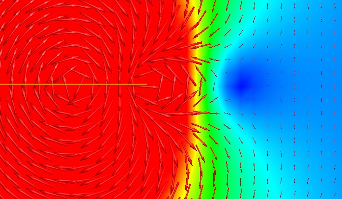
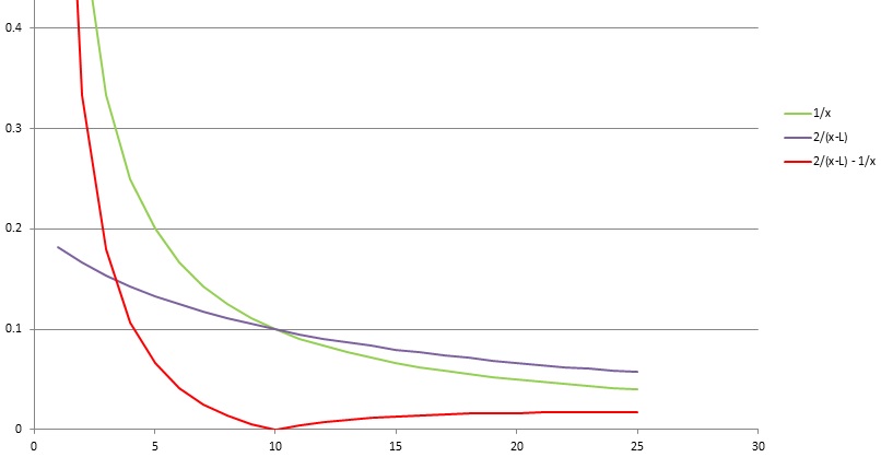
What's the problem? Of course you need to consider the vectorial nature of field strength, respectively the cancellation happens only on a single point on the x-axis. The shown curves are correct for the field strength along the x-axis.
Here's a field picture of the setup
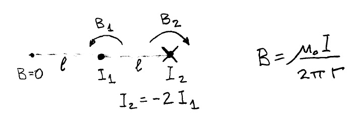
Two parallel rods carrying currents in the same direction; one 2 units and the other 1 unit. They are separated by a distance L.
Let us assume that the cancellation happens at distance a from the conductor carrying 2 units of current. The field at that point will be 2/a.
The other conductor will be at a distance of L-a but that carries one unit of current. The field at the same point will be 1/(L-a). They are equal and opposite at that point.
hence 2/a=1/(L-a) or 2L-2a=a or a is 2L/3.
This is intuitively correct because this point is twice as far as the conductor carrying 2 units of current.
You can extend this point to a line parallel to the two conductors or even a plane (?) perpendicular to the line L.
The cancellation point divides L in the inverse proportion of the respective currents. We divide L into (2+1) parts and the cancellation point will be 2 units from the conductor carrying two units of current.
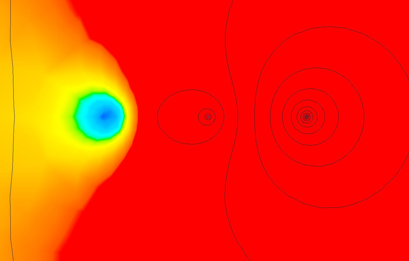
Thank you for the plot FvM! That's exactly what I would expect. Did you model jus straight wires or they are loops and port attached somewhere far away? I model wires as two loops with currents in opposite directions, take field measurements at mid-plane perpendicular to two wires - as on picture below
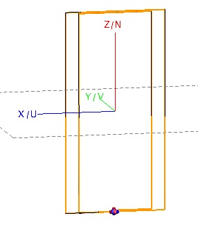
I expect to get the same picture as you plotted and I do not. Doing something wrong with software I suppose.
I did a 2D simulation (straight wires of infinite length). May the loop closure is disturbing the field.
Have you double checked that both ports (sources) are excited simultaneously in field display?
You are correct again FvM - loop closure makes a lot of difference. I am getting null now but my current ratio is 1:5!