low voltage 455KHz ceramic resonator BFO
I cannot find one on the net. any help is appreciated.
This worked for me https://www.eleccircuit.com/low-volt...rator-circuit/ but not for ceramic resonators
http://www.pan-tex.net/usr/r/receivers/sbfo.htm
I said low voltage, 1.5-3v. The link you posted uses 12v
I suggest to think yourself instead of complaining in the first place. The linked circuits are using zero Vgs bias (operating the FET at Idss), they will work well with low voltage. Just drop series resistors or voltage regulators.
This particular circuit did not work at all in my case. And I winder why, since it is a pierce oscillator, straight forward. But it did not work neither at 12v.
Maybe it is because I did not use the drain choke, I do not know what to say.
This one worked fine https://www.eleccircuit.com/low-volt...rator-circuit/ even with no buffer stage, but only for crystals.
I do not know why it does not oscillate using ceramic resonators.
This is the simplicity I am looking for, since The space inside the radio I need to include the circuit in, is very limited.
Yes, the choke is required for the design. Suppose it neither works without a transistor...
It uses a drain choke, too. Can we conclude that you didn't omit it in this case?
This oscillator may be able to operate in the range of your desired supply voltage. The LCC arrangement is not the same as a ceramic resonator but maybe you can adapt the concept for your purposes.
Thanks very much.
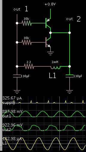
I know I said ceramic resonator at the topic, but I found that their frequency varies a lot with in-circuit parasitic capacitances. Instead of adding more components to trim the frequency, I have decided to try a 455khz transformer in which the frequency can be trimmed by the transformer alone. Here is the circuit I have tried.
With just 4 components, it works perfectly ok down to 0.5v-0.6v and the output is clean as far as I can measure on the FFT, I suspect due to the resonant collector LC. The bjt choice does not seem to be critical at all.
I think it is called a tuned collector oscillator but I am not sure, since on tuned collector, both windings of the transformer are used. Or maybe it is that kind of oscillator http://www.tpub.com/neets/book9/35c.htm
can't see your circuit .
now i got the attached circuit(?)