Replacing VFO with DDS? MC3361 80m receiver
Recently I've looked more into the receivers theory and schematics and found out that digital DDS are getting more popular these days.
I've seen simple PIC projects for AD9835, but I will most likely use AD9834 because it seems more accessible in the online store I buy.
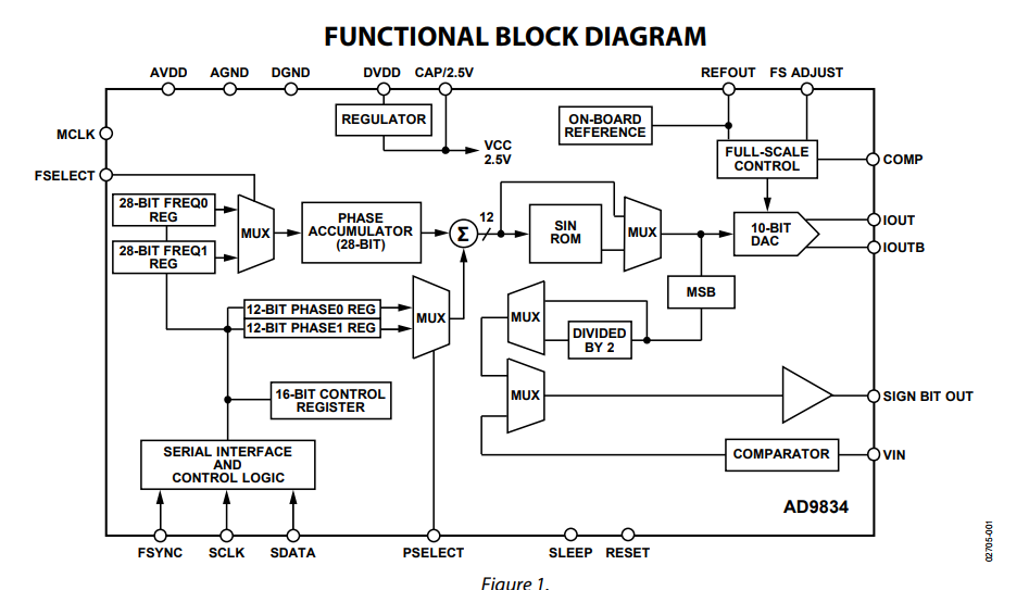
From AD9834 datasheet:
AD9834 internal block diagram:
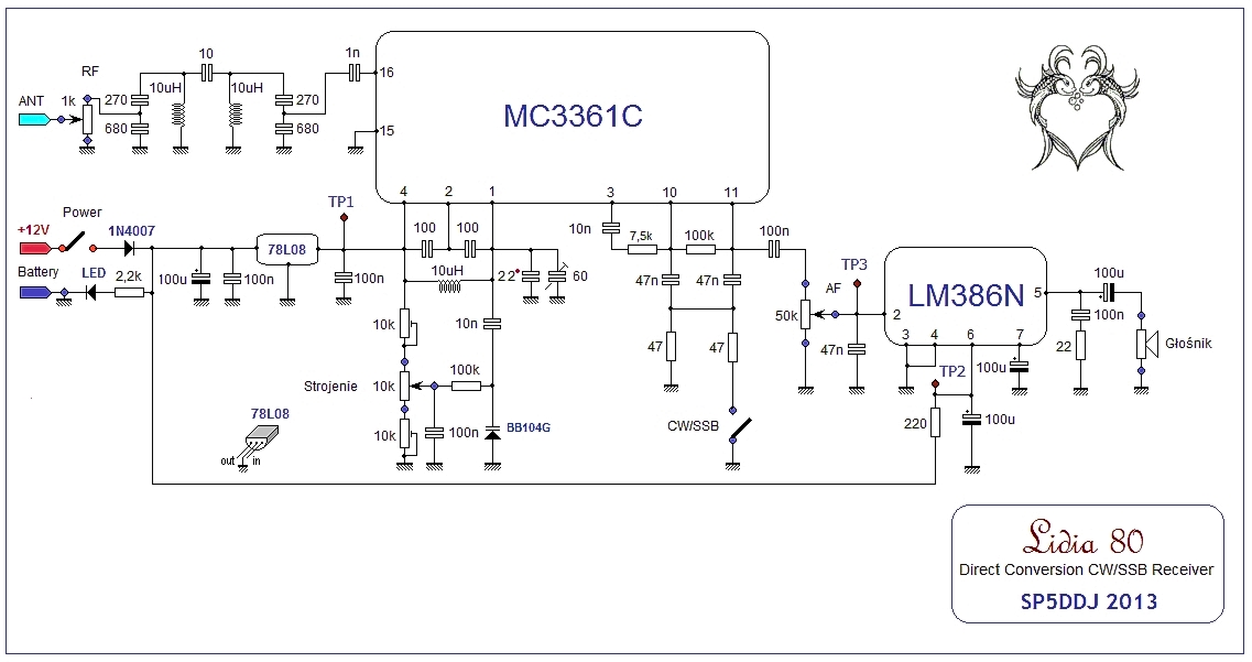
The receiver I work on schematic is here:
I'd like to replace the tuning circuit with potentiometer and varicap and use the PIC/Arduino/PC to set the frequency in a digital way. Maybe by UART, USB or simply buttons attached to MCU and LCD.
My question is, is AD9834 suitable to be used instead of VFO? What would be pros and cons of using it there? And if yes, then how exacly do I connect AD9834 output to MC3361? MC3361 has two input pins to the mixer (called "oscillator pins" in the datasheet), and AD9834 has two output pins, but what about the capacitors those pins, and ground, and VCC?
A high order low-pass filter is required to get a pure sine out of the DDS chip. Also good shielding to avoid digital noise from the DDS circuit to enter the receiver input.
On page 11-13 of the datasheet, you can see the spurious signals created by this DDS, both near the carrier and far away. Not too bad, but not as clean as a VCO.
http://www.analog.com/media/en/techn...ets/AD9834.pdf
But going back to the original post.... yes it will work and if suitably programmed you can get very precise frequencies.
You probably need to add a circuit very similar to the antenna input filter to ensure only the fundamental DDS frequency reaches the mixer as their outputs are quite 'dirty'. Don't even consider using the square wave (comparator) outputs, they are completely unsuitable.
Disconnect all the existing components from pins 1 and 2 and connect the output of the DDS filter to pin 1 instead. Pin 1 is the 'input' side of the MC3361 internal oscillator circuit but it can be used to feed an external oscillator source instead. Leave pin 2 disconnected.
Brian.