Input and output impedances of transmission line
时间:04-04
整理:3721RD
点击:
Hi All,
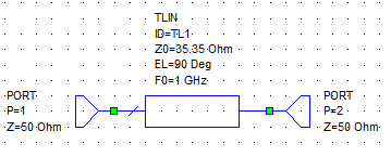
I've simple question related to the transmission line theory. Let we say, that we have such line which has Z0=35.35Ω, with electrical length equal to 90°, and it's terminated by the ports of 50 Ω. I'm wondering why in AWR simulator input and output impedances of the TL are equal to 25 Ω. According to quarter wave equation, I should obseve value of 35.35 Ω (when Zin = Zout).
Best Regards,
E.
Simply you can not understand basic theory at all.
Surely relearn with kindergarten level text book.
Zin=R0*R0/Zload=35.35*35.35/50=25
Try a simulation with 180°.
Start to sweep the length from 0 to 180 degree, you'll observe that when the TL's length arrives to 90 degree, the real axis will show you 25 Ohm.


Input impedances transmission 相关文章:
- Different Input/Output matching
- How do you choose input power while doing loadpull?
- Why an input inductor required in all GPS LNA?
- Input and output impedance matching in Distributed amplifier
- In distributed amplifiers, is it total input capacitance of the gain stage or Cgs
- curve fitting for input and output matching