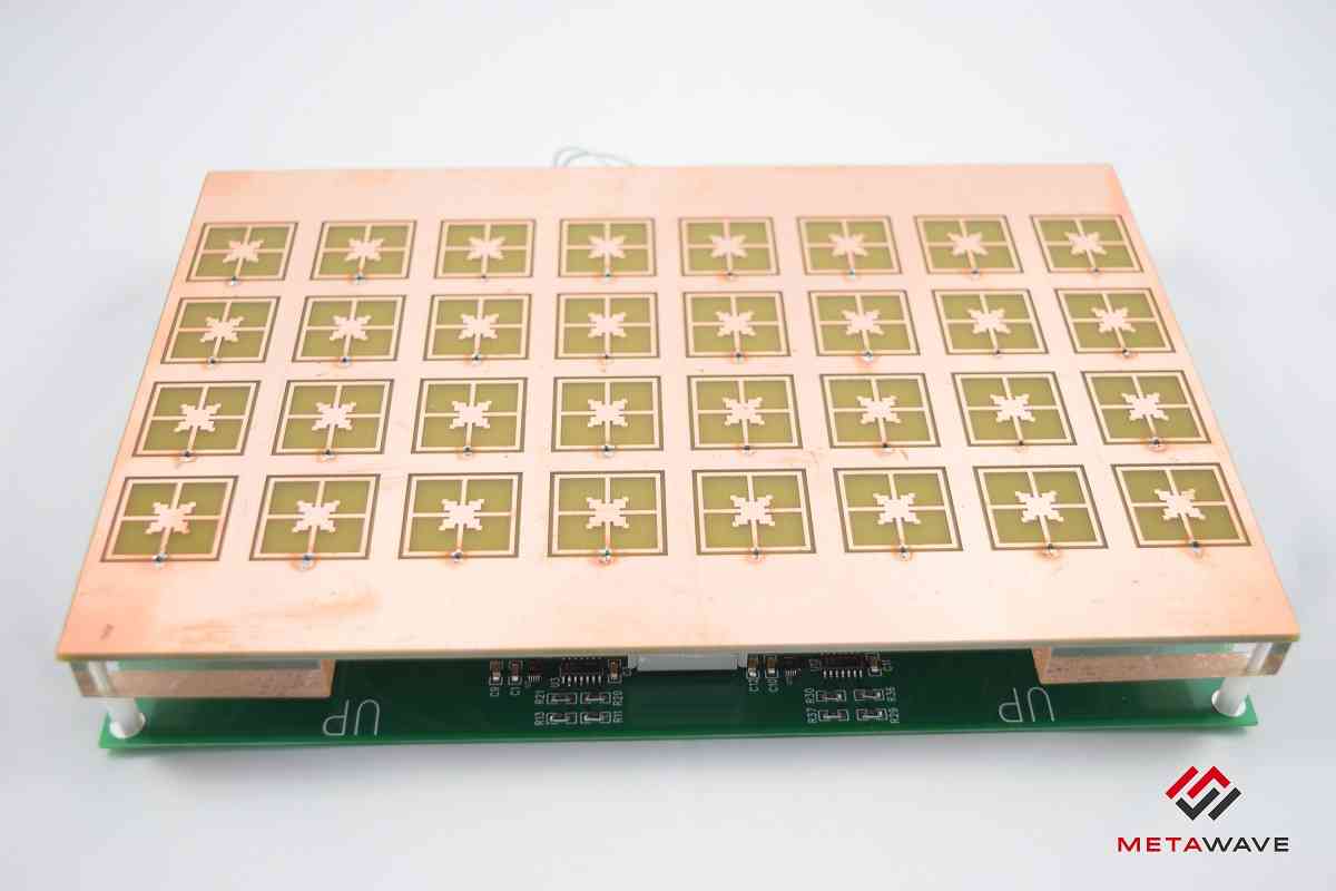
Metamaterial unit cell structure of Metawave's radar used for beam steering.
Is it metamaterial radiating element + varactor diode, or it is metamaterial phase shifting layer with some patch radiators underneath?
references:
https://www.autosensorsconf.com/site...ave_Achour.pdf

According to https://www.liteon.com/storage/docum...2017-10-04.pdf
beamwidth is 1° ! Kind of small for 8x4 array. It is possible that array is under metamaterial surface and have more elements.
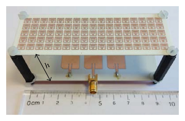
Found something similar (maybe) in article "Design of High-Gain and Beam Steering Antennas Using a New Planar Folded-Line Metamaterial Structure, Minh Thuy Le, Quoc Cuong Nguyen, and Tan Phu Vuong"

As you can see, there is actual patch antenna underneath, and some metamaterial layer on top.
Frequency is 5GHz, distance between patches and metamaterial surface is h=30mm, which is approximately half-wavelength at 5GHz. 30mm is huge, but Metawave's radar frequency is 76GHz to 81GHz. At 76GHz wavelength is around = 3.9mm. Then similar distance between metamaterial surface to patch array will be around 0.5*3.9= approx 2mm. This is tiny distance and actually both layers may be placed on a single multi-layer PCB (similar to image of Metawave's radar)
Full article on 5GHz beam steering is available online:
https://www.hindawi.com/journals/ijap/2014/302580/
https://www.hindawi.com/journals/ija.../302580/fig23/
metamaterials are useful for slowwave structures. It is possible that they are using that property to make the antenna "look" like the antenna elements are spaced out further electrically, than they physically are.
On the photo it looks like there is varactor at the bottom of each "unit cell":
https://www.autosensorsconf.com/site...ave_Achour.pdf (page 6)
And state steering 3 degree beam in wide field of view.
I want to know how "Active MTM elements to cover 360° phase shifts" are achieved.
