Optional antenna placement
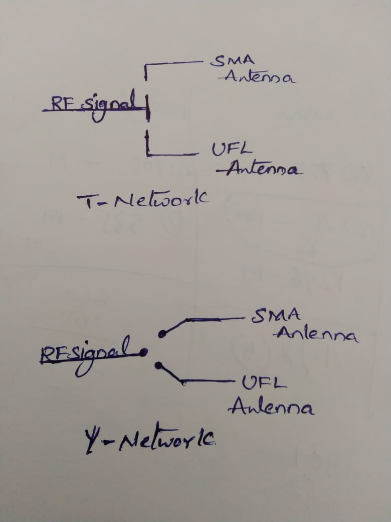
I'm planning to place two antenna's UFL and SMA supported on my RF board . among them one is optional for a particular time. So , I've two different approaches or placement methods , one is T-Network method and the other is Y-Junction method .
Can anyone please mention which one is the best approach when i'm transmitting through that antennas.
What is operation frequency? I imagine SMA-connector may be matched to to look like half-wavelength open-stub resonator to minimize mismatch if frequency is pretty high.
Really not sure what is Y-junction and how it differs from T-junction in your case, by pcb lines shape? On your image there are gaps and three ports have no connection.
I would use nice tiny SPDT chip, something like: https://www.mouser.com/datasheet/2/1...EN-1226065.pdf
The operational frequency is around 1GHz , Thanks for the suggestion about switch usage , But here I don't want to use the switch that's why I came across these options .
Where The difference between the T-junction and Y- junction are in the layout pcb lines only.
If I considered the T-junction, Let's say I have shorted the UFL antenna path as conducting path for RF line , Is there any chance of leakage of Transmission power from the other end of T-network in SMA path. (I'm expecting, we will arrive with some transmission power loss ) , can we mitigate that transmission loss with Y-junction placement ?
It's not clear what's the actual difference between both drawings. So I'll answer differently.
I presume both involves a jumper, e.g. a 0-ohm resistor chip. The best solution has the least transmission line discontinuity and no open stub. Or the discontinuities must be compensated in the already used impedance matching.
There's no real problem at 1 GHz.
This may be useful, frequencies are not far from 1GHz:
https://www.microwavejournal.com/art...-as-a-combiner
http://www.rroij.com/open-access/per....php?aid=41369
http://www.rfwireless-world.com/Term...RF-Switch.html
Are both antennas operating at the same frequency? If so, wouldn't the power split evenly if your antenna impedances (50 Ohms) are the same? Without some sort of switching element, it seems both antennas will be energized at all times.
place ufl connector on the trace which will reduce the extra stub. there is one Microwave Coaxial Connectors with Switch available with ufl size .
The internally built-in mechanical switch separates the RF circuit and ANT circuit, so that the circuit can be measured without any mutual effect using a dedicated probe madeby Murata. Except when measuring with probe, internal mechanical switch is connected, so RF circuit and Antennacircuit are connected.
https://www.digikey.in/product-detai...0-1-ND/1775924