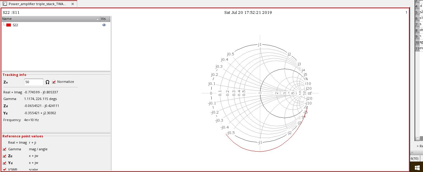
Why S22 curve is like this
Anyone know any other good book for stacked transistor amplifier other than Millimeter-Wave Power Amplifiers by Jaco du Preez, Saurabh Sinha
Not wrong at all.
Simply due to Y12.
Calculate Yout by hand from your small signal model of MOSFET.
https://www.edaboard.com/showthread.php?385490#3
I want to have positive resistances. I am wondering how to make it possible
You amplifier may be unstable..
Yes it is, but If I have to keep degenerative inductor it needs to a huge value. I tried with small inductance values but still it is unstable.
There are methods to stabilize an amplifier such as connecting a resistor at input and/or at output.A negative feedback may also stabilize the amplifier..
Surely learn and understand following.
https://www.edaboard.com/showthread.php?384656#4
I have seen in a book, a capactior is also used. I am still wondering how bias is provided when capacitor is kept in the signal path as shown in the figure.
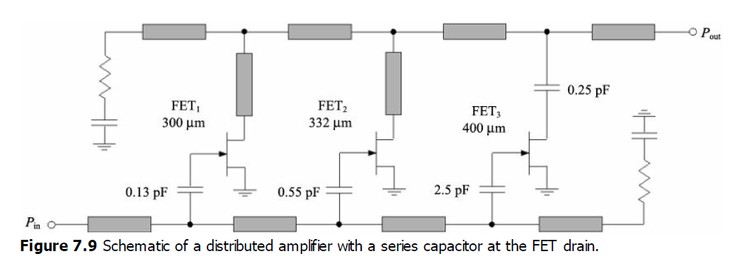
Simply bias circuitries are not showed.
That’s all.
I know that bias is not shown. If at all bias is connected, where should it be connected?.
Anyway, I found out where It should be connected without disturbing biasing.