How can Transmission line does not see Stub?
Here you can see my design (it is only schematic and the values do not correct)
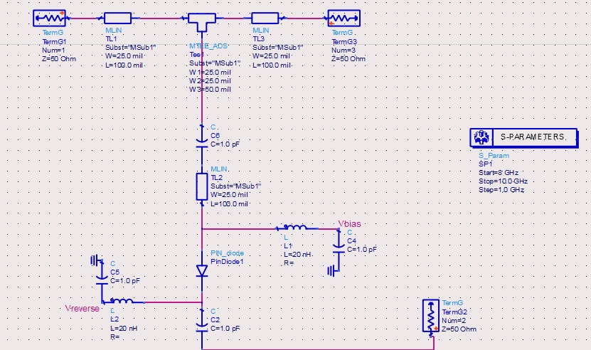
AGAIN my values in schematic do not correct
my first question from this design
as you can see some times diode should be off at this time all of power should receive from port 1 to port 3
but when that diode is off Tl2 is like an Stub and change Antenna Impedance
how can i do something that port 1 only see port 3 and i have not any change impedance and power dissipation in port2?
The purpose of the circuit isn't quite clear.
First, point, you get impedance mismatch and reflections at Tee1 if the diode is turned on.
Isolating the inactive stub (with diode off) is the easier task and can be achieved by increasing the effective stub length to λ/2.
yes
it is my second question
when diode is on all of my power should pass from diode and nothing from antenna should be propagated port 2 is GND and all of my power go to ground
when diode is off i work in high power (200W) and when it is on i work in small signal (1mw)
That's hardly possible with this circuit.
Sounds like you want a SPDT switch (at least two pin diodes) instead of a SPST. It's however not clear what's in- or output in your circuit.
It should be SPDT but I cant find any diode with this Spec so I looking for new idea
When I work in large signal all of my signal from port 1 should go to port 3 (300w 9G)
But when I work in small signal (1 mw) all of my signal should go from port 1 to 2(short circuit)
I cant find any diode from MACOM or Skyworks or Microsemi that they can work in that area
Do yo think can I do ?
What do you mean with "short circuit"? A short (reflection factor = -1) would reflect the wave back to the input. An absorber port should have 50 ohm impedance.
As mentioned by others in your previous similar thread https://www.edaboard.com/showthread....87#post1672087, the power level is probably not achievable with diode switches.
I read in a Skyworks application note, that PIN diode switches can work up to 1 kW CW. But do they at 9 GHz?
No I searched in https://www.richardsonrfpd.com/Produ...20PIN%20Diode#
But I can not find any thing
I don’t think only abour diods I searched for mechanical relays and other things but I could find nothing
Hello
I like to build a mismatching in some times for output a circuit (to Antenna)
It works in two area
First it should be match with antenna in 300W in 9GHz (diode off)
Then it should be mismatch in 1mW in 9GHz (diode on)
I build a circuit with a diode in SPST structure (undoubtedly I should have SPDT and it will work better than SPST but I can?t find any diode for put in power line so I have to use SPST)
1- After input I put a line with lambda/2 length
2- I put diode circuit here
3- Here I put radial stubs lambda/4 lines and etc.
4- I put instead diode a Resistor that I change the amount in forward bias in 1 ohm and in reverse bias in 100000ohms it goes to ground
5- I put in other way Antenna
6- It works not correct
What is(are) my mistake(S) here?
result aren't good
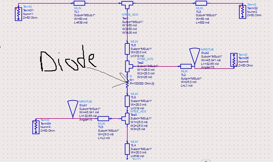
Your circuit has at least 4 ports without any annotation. Which is input, output, antenna, passive absorber?
port 1= input
port 2 = Antenna and output in highpower
port 3 = is Ground it is under TL4 i didn't put any absorber
without absorber in the end of diode circuit go to ground and i think with this line i want to destroy my S21
and i looking for other idea may be my design doesnt work correct so i make other thread
because nobody give me an answer so i like to simple my question
i change that to ideal and put instead radial stub cap and what you see
but it is again wrong
i know something in TL2 or C2 is not correct but i dont knowa whaty
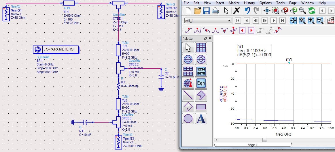
C12 is a short at these frequencies, and TL2 transforms to an open at CTEE1.
If you want to have a DC feed at CTEE2, add a lamba/4 line (narrow, high impedance) and then the radial strub.
thank you
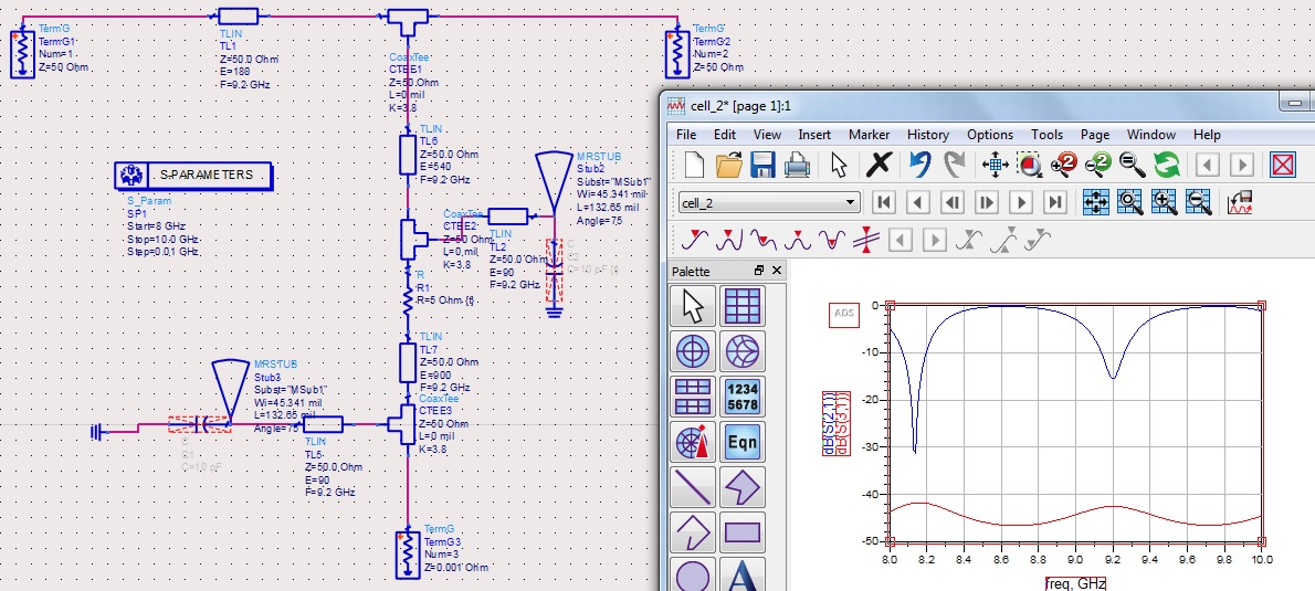
but i cannot understand why i add electrical length with factor of lambda/2 some notch appear for example (900 and 540) near 8.1GHz but when i change to 180 they disappear
how can i calculate them?
You need to work more carefully!
Now your TL2/MRSTRUB is an open circuit (hopefully) and you line can "see" the 540° long TL6 plus 900° (ninehundred degree) long line TL7, which transforms the 1mOhm at port 3 around the Smith chart. Strange design.
BTW, using that port impedance at port 3 makes no sende to me. It is difficult to realize that short in hardware, and mixed impedances in S-parameters are difficult to interpret.