Captured field by Array Antenna
Here antenna element size is "a" and spacing between element is "d".
Antenna element size "a" is comparable to spacing "d".
What position of incident field is captured ?
Feeding point ?
or some averaged field ?
The total field of an antenna array is determined by the vector summation of the induction fields radiated by the individual antenna elements.
This assumes that the current in each element is the same, ignoring coupling between antenna elements (mutual coupling).
In practice, the separation (mutual coupling) between antenna elements is a critical characteristic of antenna arrays.
The array inter-element coupling effects may increase the sidelobes and the main beamwidth, appear of shifted nulls, and array blindness in some scan angles.
Mutual coupling is an important problem when the number of antenna elements is small.
In the example attached, 3 patch antennas forms an antenna array. The distance between centers of the antennas is comparable to the width of each patch, so the mutual coupling between antenna elements is relative high.
The feed phase difference in degrees between antennas in the 3 cases is: A=(0,0,0), B=(0,45,90), C=(0,90,180).
Can be seen that even with relative high mutual coupling between antenna elements, the array can be steered reasonably, with some grating lobes at high angles.
No.
Only one element is active at same time in spatial sampling.
Active element is changed by switch which is connected to receiver.
Coupling can be canceled by diagonalization of impedance matrix of array antenna.
Not sure if there is a unique valid answer. For antenna simulation software that I know, the location of the phase center for far field pattern is arbitrary (offset doesn't change angular pattern) and not a simulation result. In addition, your question seems to refer to the near field, where things get complex (E and H not perpendicular) and depend on the actual antenna type.
Fields are simple.
E is perpendicular to element at surface of element.
So element captures parallel component of E which exists if element does not exist there.
I think element captures averaged tangental field over element not point field.
This resembles to integral sampling of time domain.
If that's so simple for your (unknown) antenna type, I'm surprised you even asked here. For the antenna designs that I work with, simulated E fields in the near field are a bit more complex, and vary a lot across the antenna.
But averaged might be a reasonable estimate. Good luck!
Maybe depends on antenna element type? Single patch consist of 2 radiating edges spaced by half-wavelength wide transmission line, so it looks like 2-element array in E-plane. Patch may be cut in half and shorted with vias, and still work with a single radiating edge. So maybe "averaging" in E-plane would differ from H-plane for patch radiator.
Seems that you know ALL the answers...before placing the questions here...
No, I have no answer.
We can get propagation path length difference as signal difference at feeding point while element's size "a" is comparable to element's spacing "d".
I can not have clear explanation for this.
Here I assume
- Single frequency
- Perfect synchronized local signal between TX and RX.
- Plane Wave is arrived at RX
- No mutual couping between elements or Single Antenna which is moved physically instead of Array.
Some related thoughts, hope it helps somehow. One problem i see: why "Perfect synchronized local signal between TX and RX"? TX frequency may fluctuate with time, just need to ensure TX is stable enough during sampling through elements 1,2 and 3. You may try point source instead of plane wave and think in this direction. If point source is too close, then results are not correct.
Or imagine playback antenna radiation backwards in time. So antenna element receives only "spherical" part of plane wave, maybe someone with more knowledge in this area could explain.
No.
Elements 1, 2 and 3 are not sampled at same time.
Consider phase of complex baseband signal not RF signal at Receiver.
Your question is not clear. Is this about the far field?
How is your scenario different from school math used to derive antenna array pattern by superposition of individual antenna's complex signals?
Not beam forming.
It is not phased array antenna.
See https://www.edaboard.com/showthread....tion-Detection
http://dev.ti.com/tirex/content/simp...a/ble_aoa.html
Understood, but I think it makes sense if you study phase array math, which is derived by superposition of the individual signals. It looks very much like your case: plane wave excitation to antennas with that position offset, calculate all the individual signals. The only difference is that you leave out the last step (adding them up). The rest of the math should be identical.
Still you can not understand.
I understand such basic things.
All elements are not active at same time.
Only one element is active each time.
Rarher concept is close to SAR(Synthetic Aperture Radar) a little.
Concept of Sampling of this element is close to windowed integral sampling using switched capacitor circuit.
It is not an impulse sampling which samples data at instantaneous time point.
Ok ... Again the question: What is your distance to the target/field source? Is that far field?
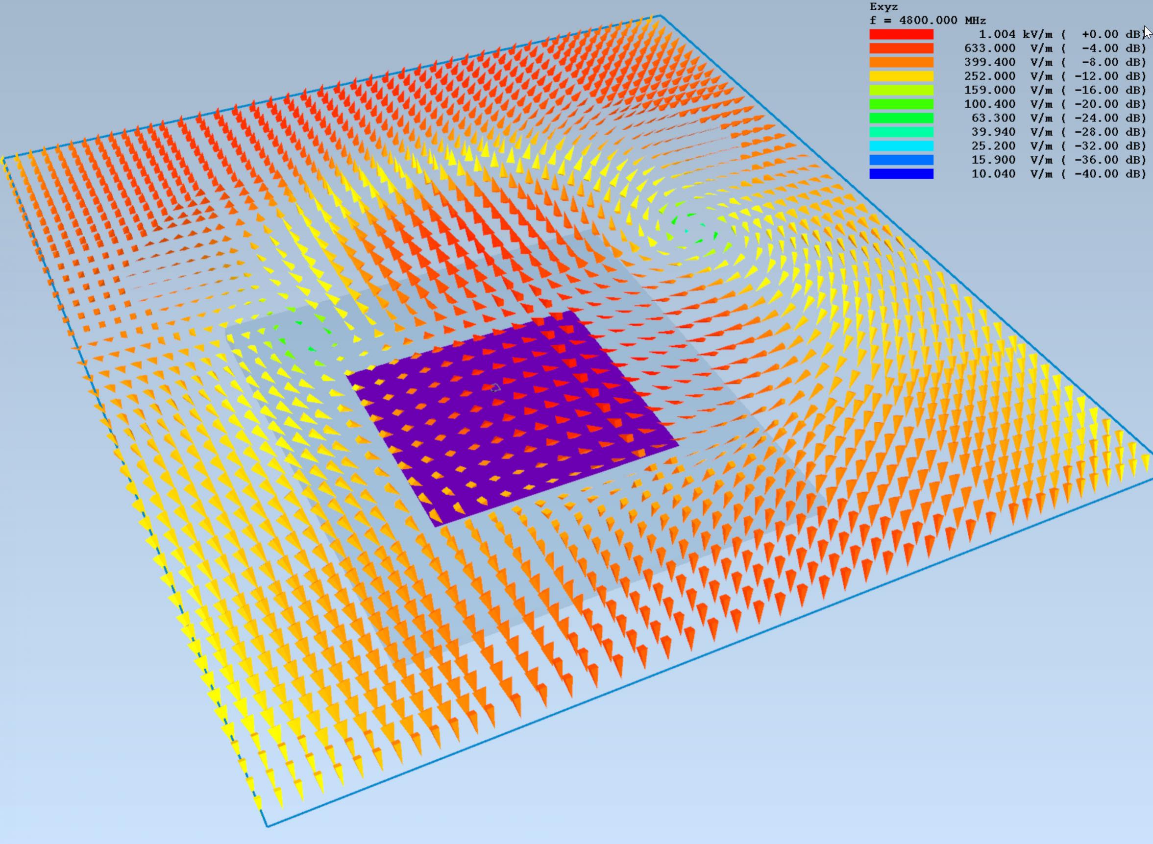
In the near field, the fields are rather complex, unlike your assumption above. Here is the E field at approximately lambda/4 in front of a patch:
As far as i know simple MIMO radars perform semi-simultaneous sampling, and separate TX/RX antennas are used.
For your configuration it will be 6 patches: 3 TX patches + 3 RX patches.
Some kind of SP3T switch constantly toggles LO between 3 TX antennas with 3x rate of sampling frequency
3RX patches have separate receivers with the same LO. IF1, IF2 and IF3 outputs go to sample and hold circuit and 9 channel ADC or very fast 3 channel ADC.
Digitized data then separated to 9 channels. Because of semi-simultaneous sampling there would be small phase shift because of time lag between channel 1 and 2,3; 4 and 5,6; 7 and 8,9. Time lag is 1/(Fsampling*3) sec.
For example, semi-simultaneous sampling. Need to record 256 samples at Fsampling for further signal processing.
Following sequence repeated 256 times at frequency Fsampling*3.
TX1 on, fast ADC saves RX1 to CH1, RX2 to CH2, RX3 to CH3
TX2 on, fast ADC saves RX1 to CH4, RX2 to CH5, RX3 to CH6
TX3 on, fast ADC saves RX1 to CH7, RX2 to CH8, RX3 to CH9
Or something like that. I think basic idea is right.
So phase correction may be required if TX switching speed is close to 3*sampling rate. Higher TX switching speed gets more close to simultaneous RX sampling.
If antenna elements are identical, I think they may be considered as "black boxes" with some identical phase shift and amplitude attenuation, and do not affect relative phase measurements between elements.