Transformer - wind your own
12Vrms
0.2VA
60Hz
Is this something I could wind myself in an hour?
What core should I use and roughly how many turns would be required.
I searched for a transformer like this but did not find anything. Perhaps I'm not searching in the right place?
At low frequencies, it's important to have metal mass to increase inductor value. At 60 Hz a reasonable Henry value is between 1 and 10 H.
Combined with this there needs to be a sufficient number of turns. Larger core, fewer turns.
As you can see, it becomes a question whether a transformer is worth the trouble for a small power level as .2VA. You can reduce a few parameters if you don't mind losing inefficiency. Example, copy the old tactic of using a soft iron nail as your core. A half inch diameter suits the purpose better than 1/8 inch diameter.
The wire can be very thin since it only carries 17 mA. Wrap two pieces of wire simultaneously.
Do you have a variable speed drill? Spin the nail and it will wrap the wires with minimum effort.
There are some low cost 1:1 high impedance audio transformers on e-bay that might do the job.
I have no idea if it can handle 12v at 60Hz without core saturation, but for the price it would be worth a try.
http://www.ebay.com/itm/Audio-Signal...cAAMXQH6BRE~aj
I found what appears to be a similar transformer in my "transformer box", looks identical (except one side is center tapped), however I don't know the specifications. I made a few measurements as follows.
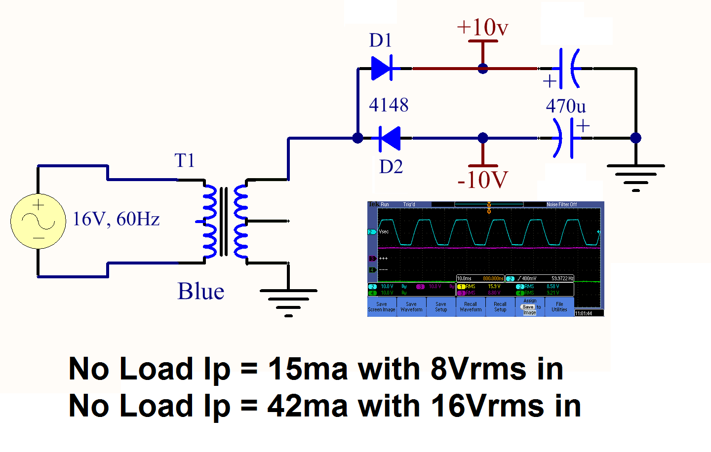
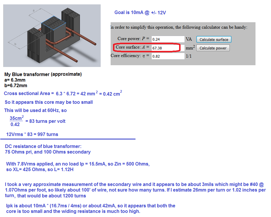
With 8Vrms in and no load the input current is 15ma, the input current increases to 42ma with Vin = 16vrms
I connected a couple of diodes and capacitors as shown below and I have a ±15V power supply (with no load). If I could pull 10ma from this I would be good to go.
If I load this to about 10ma (that's what I need) voltage drops to about 8V (too low) and the secondary ac waveform is severely clipped, is that due to core saturation?
I'm reasonably close to a solution, perhaps an audio transformer with slightly different specifications would get me there, numerous to choose from with slightly different input/output impedance. How do I go about determining what I have and what would likely be closer to what I need?
Your bipolar supply is the same principle as a bridge voltage doubler. It appears capable of a maximum differential of 16V at 10 mA.
To provide this, the secondaries must produce pulses of current at 150 mA or more. Saturation is likely because you report clipping.
Do you have another transformer like it? Then you can connect the primaries in parallel, the secondaries in series. Use Villard doublers to connect them at center 0V ground, if you require that.
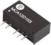
Another completely different way to do this would be to buy a standard 1 watt isolated power module.
These are available in a whole range of different combinations of dc input and dc output voltages.
This particular one is 12v input with +/-15v outputs.
Check out e-bay, search for "1W isolated"
http://www.ebay.com/sch/i.html?_from...lated&_sacat=0
Its a bit of a mixed bag, but there are a couple of +/- 15v output types there.
Not well considered. Saturation would also show at no load. Seeing the "clipped" waveform in loaded state indicates too large transformer windings resistance in combination with the rectifier and filter capacitor, just normal behavior. Measure the transformer parameters and you can predict the waveforms in a simulation.
Calculating transformer windings is easy. Calculate 42 cm2 windings/core cross section for 50 Hz or 35 cm2 windings/cross section for 60 Hz as a starting point.
FvM
I'm not sure if my calculations, estimates, approach and conclusion (see below) are valid, please comment. I'm somewhat flexible on primary voltage it could be anywhere in the 6-24Vrms range.
may I ask if your requirements are;
time? 1hr, times up.
cost? how many?
learning how to design magnetics? do some math
- The impedance of the transformer with no load must be high compared to your load to give somewhat ideal transfer and loading characteristics.
- Pmax=ξ*VA =Vrms2/Rload so for ξ=1, Rload= 122 / 0.2 = 72 Ohms
- Meanwhile the magnetizing inductance at 60Hz to be much great than the load means much greater than 10mH.
- This would require a high number of turns or much higher permeability core.
purpose?
If using to rectify into DC the load becomes the ESR of the diodes and Cap during charge and then open circuit during discharge.
Since %ripple can be equated to Iavg/Ipk = % duty cycle... it is equal to Impedance ratio % {source / load}.
In order to provide low conduction losses I2* R, the winding source resistance must be very low to achieve desired % ripple, and % load regulation.
make sense?
try again. This time with purpose and constraints.
I will start with the purpose. Isolated +/-12Vdc power supply for an A/D circuit. I will need about 500 in the long run, but only 1 for testing immediately. The device already has a low power transformer with 12V secondary that can be used to drive this isolation transformer.
Cost, preferably about S2, this is why I'm exploring the use of an OTS audio style transformer (eBay seems to have a fair selection with some priced in this range). Actual power transformers from Digi-Key etc. are typically larger and more expensive.
I only need about 10mA
You might be better off using a separate transformer with 230 volt primary to power your a/d.
The reason being that as transformer size increases, cost increases because obviously more iron and copper is needed.
What is less obvious is that below a certain size, cost also rises because of the greatly increasing difficulty of manufacturing.
Extremely thin wire and the many thousands of turns required make the task very difficult.
You will probably find that the lowest cost, mains transformers available will be around the 3va to 5va size, and smaller than that cost will increase.
That sounds excessive for only 250mW of dc, but as you have already discovered, driving a rectifier with a capacitor load can be rather demanding on a transformer.
The numbers do not add up. You only want to pay S2 to buy each transformer but you are willing to spend 1 hour of labor to make one.
I would be happy spending an hour making one for testing purposes, 2-3 hours for that matter. however when I need to purchase 500 or more I hope to get the price down to S2 or so. I'm obviously not going to personally wind 500 of them.
Back in this thread i gave a link for S5 transformers qty 1, in qty 25 they are about S3.
https://www.edaboard.com/thread347951.html
The only other realistic alternative is to design your own switching power supply. You would only need one transformer core like a toroid that would have few turns and you could wind them all yourself. If you have a free source of low voltage DC to power the SMPS all the better.
You wanted 10 nodes. You could have all 10 nodes on just one toroid.
FlapJack,
I took another look at the link you provided (this time ignoring qty 1 pricing) and this transformer looks like a good fit. Thank you
http://www.digikey.com/product-detai...574-ND/3986373
Transformer wind 相关文章: