loop antenna simulation in HFSS
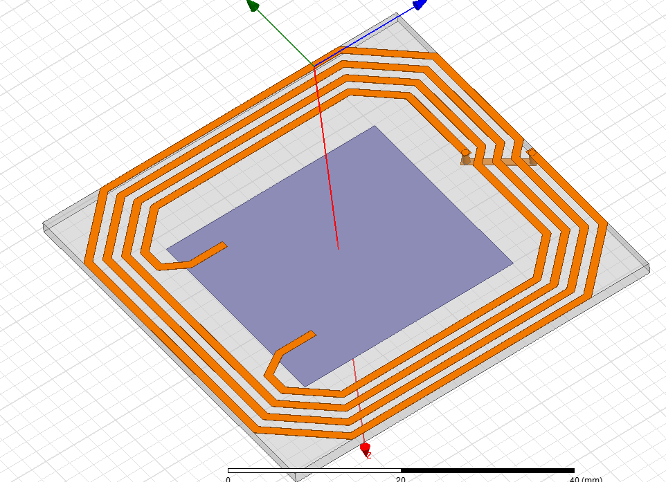
I made a loop antenna like this. I simulated it in Maxwell and I found R and L. Now I want to simulate it in HFSS.
I do not know how can I simulate it and How should I define wave-ports. I want to find Z to compare.
I would be more than happy if you help me with this.
Welcome Ata_sa16,
Is the solid blue patch a conductor? If so, you probably want to connect the two ends of the inductor to this patch by lumped ports. Wave ports probably wouldn't be of much use in this setup.
Good Luck!
Actually thats extra. I will remove it. I know i have to use lumped ports but the problem is how can i set up the simulation. I tried many times but i face error and even when it works it gives me wrong data.
Defining lumped port is complicated. I guess i have to use 1 port and define inductor's other terminal as ground. But i dont know how to do it
So you just have a single conductor, and you want to extract the effective impedance?
I would bring the two ends closer together and cover both with a lumped port. Then you should be able to obtain Z(1,1). Keeping them far apart could work, but I'm not sure how well.
Yes you are right. The problem is, when i define 1 port for 2 conductors it gives an error that more than 1 conductor in port :(
It would probably help do do a driven modal simulation, rather than a driven terminal.
i used driven modal simulation.
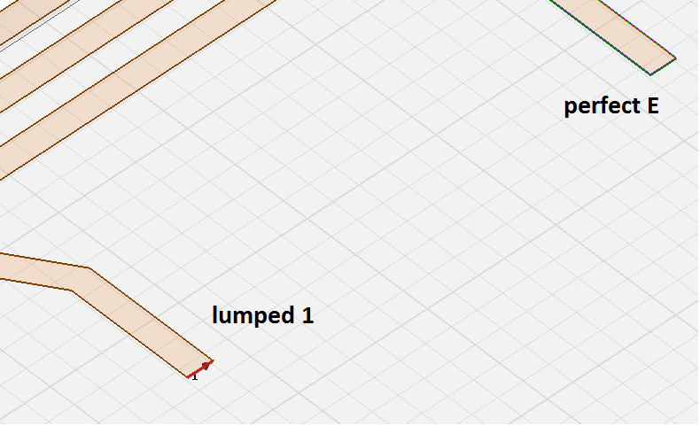
it does not work
I need a manual which explains how can i put one port on my antenna and define other port as ground and observe Z11
Hi Ata_sa16,
Your problem is readily observed from your attached image. A port must cover two conductors if you're planning on exciting a TEM mode. Do not use one port per conductor.
I made like this to make it more realistic. now I have to put ground and my terminal in 1 port. This time, my problem is I dont now how to define it !
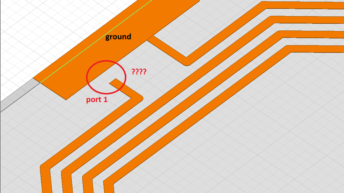
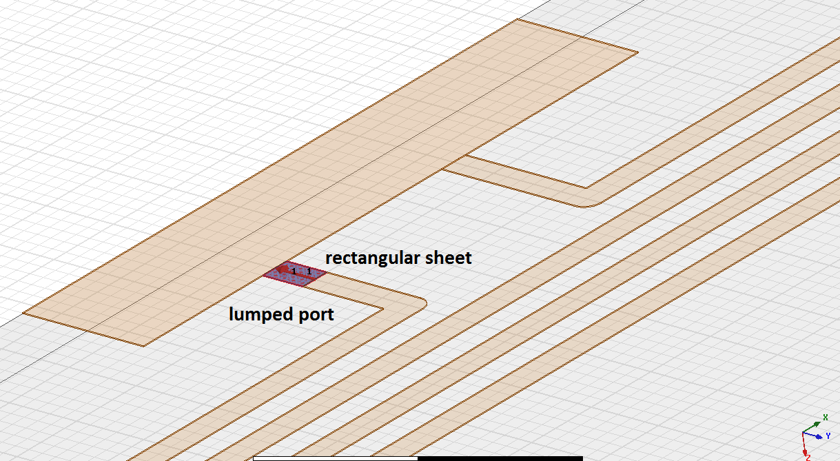
Finally I set it up like this. I do not know if it is correct or not.
You didn't mention frequency, but the picture looks like low frequency, e.g. 13.56 MHz. A small coupler coil can be treated as pure AC-magnetics problem (no EM waves and coupling to far field involved). Also the difference between single ended and differential port doesn't really matter, your ground copper pour increases at best the parallel capacitance by a very small amount.
In other words, it looks like you are complicating things without a purpose.
yes 13.56 MHz. I do not know I defined port correctly or not.
That ground plane does not matter I wont include it in fabrication. This is just for test
That looks like it should work, does it give the right Z11?
12 hrs simulation and it is kind of stock. :(
Finally, wrong result -> Z11= 1.2 - 190j , imaginary part is negative !
This is my simulation setup, maybe it is wrong.

I defined lumped po
There are many ways to setup an EM solver wrongly, so even guessing about the reasons seems pointless.
A simple AC magnetic solver like Fasthenry gives the correct input impedance in a couple of seconds.
If you didn't confuse meters with millimeters, negative reactance means capacitive load = no connection between port and coil.
Thank you for suggestion. I have already extracted the values in Maxwell. The thing is, I dont need the values. My purpose here is to compare them with maxwell results and learn HFSS.
I think my problem is, I cant define lumped port correctly. I dont know what is the correct method for it.
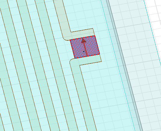
For port
1- I put a rectangular sheet between edges of two terminals.
2- I excite it with lumped port
3- I define a line from one edge to another
Lumped Port
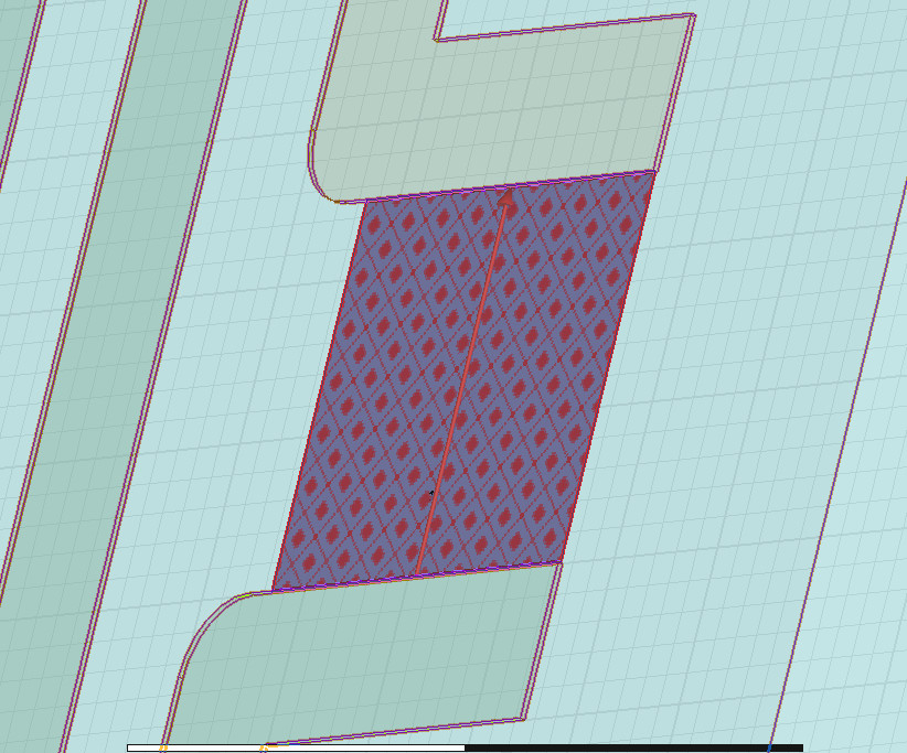
Finally it worked 2.6 + 189j which gives L=2.2uH.
I fabricated and tested this antenna before L is 3.3uH. I think HFSS does not calculate coupling between wires.
Anyway, Thank you so much guys for your amazing help.
I appreciate.
HFSS is a full-wave solver; of course it does.
I would try increasing the convergence, and see if you get a different result. If the simulation is sufficiently converged, you should trust HFSS over other circuit-modelling softwares.
How can I increase the coverage?
You can increase the convergence by changing the convergence criteria of the analysis setup. Under HFSS->Analysis Setup->List (or under 'Analysis' on the left), select the setup you created and view its properties. The number of passes should be relatively high (> 20), but importantly, you should set Delta S to be sufficiently low (< 0.01). You can have the simulation increase its convergence arbitrarily by setting Options->Minimum converged passes to be larger than 1 (I typically use at least 2).
