How can I create the loop of a circular loop antenna?
时间:03-29
整理:3721RD
点击:
I want to model a loop antenna, but are not sure how to draw the loop. I have seen this done in the past, and if I recall correctly, a circle is drawn, and then that swept along a arc. But I can't seem to find out / recall how to do it.
I did think of drawing a torus, then chopping a bit out by drawing a box over the torus, and doing a subtraction. So essentially putting a cut through the torus.
Any ideas? I have access to HFSS 14.
I'm guessing driven model with a lumped port is optimal. I say that, as that is what is used on a dipole in the HFSS antenna design tool. This seems pretty close to that sort of thing.
I believe you misunderstood me - note I mentioned the word "torus"
https://en.wikipedia.org/wiki/Torus
I want a loop like a torus, but with a gap - see image. I'm looking for something to fabricate out of copper pipe, not something on a PCB.
I simulated that with a circumference of 1.0 m, and 10 mm diameter tube (I used a perfect electrical conductor for the simulation. The resonate frequency is around 130 MHz, but varies as I change the solution frequency even slightly, so I'm not entirely trusting of the results of the simulation. The problem with a lot of EM simulation software is that it is easy to make a mistake, and those mistakes are far from obvious.
What I done there was
I don't believe however a torus is the right way to do this - I think a circle should be swept around an arc of 340 degrees or so. Therefore the loop has a gap. I just don't know how to set it up.
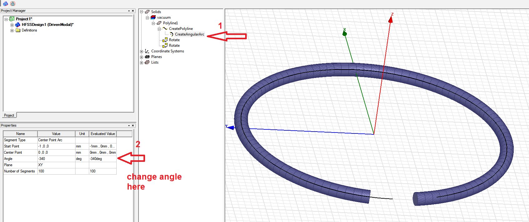
Here you can change angle:
I did think of drawing a torus, then chopping a bit out by drawing a box over the torus, and doing a subtraction. So essentially putting a cut through the torus.
Any ideas? I have access to HFSS 14.
I'm guessing driven model with a lumped port is optimal. I say that, as that is what is used on a dipole in the HFSS antenna design tool. This seems pretty close to that sort of thing.
try this:
https://www.youtube.com/watch?v=yWftIKlIB8c
but its better to download and install Maxwell 14.0 for this purpose.
Once I did and I simulated my design. However, when I fabricated it, the result was different than that I obtained in simulation. (
So after weeks trying and searching about it, I concluded that I cannot trust these simulations.
https://www.edaboard.com/thread352576.html

I believe you misunderstood me - note I mentioned the word "torus"
https://en.wikipedia.org/wiki/Torus
I want a loop like a torus, but with a gap - see image. I'm looking for something to fabricate out of copper pipe, not something on a PCB.
I simulated that with a circumference of 1.0 m, and 10 mm diameter tube (I used a perfect electrical conductor for the simulation. The resonate frequency is around 130 MHz, but varies as I change the solution frequency even slightly, so I'm not entirely trusting of the results of the simulation. The problem with a lot of EM simulation software is that it is easy to make a mistake, and those mistakes are far from obvious.
- Create a document in OpenOffice, and you see if the text looks right or not.
- Edit a photo in Gimp, and you can see if it looks right.
- Perform an EM simulation in HFSS, and it is far from obvious if the results are correct or junk.
What I done there was
- Draw a torus
- Draw a box that overlapped the torus
- Performed a subtration using Boolean -> Subtract.
I don't believe however a torus is the right way to do this - I think a circle should be swept around an arc of 340 degrees or so. Therefore the loop has a gap. I just don't know how to set it up.
I made u this tutorial, I hope it helps you.
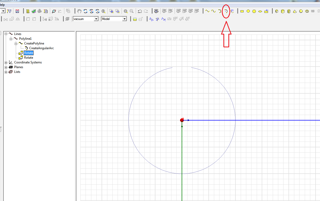

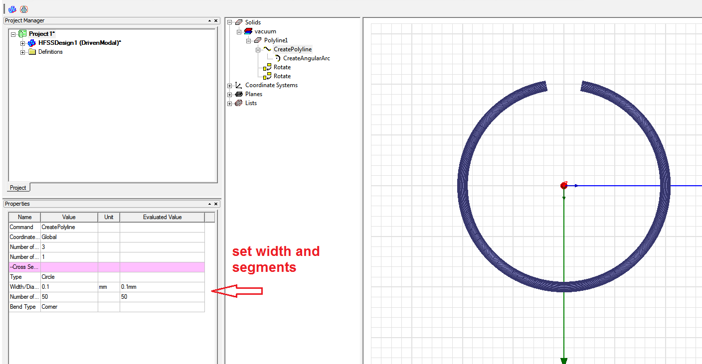
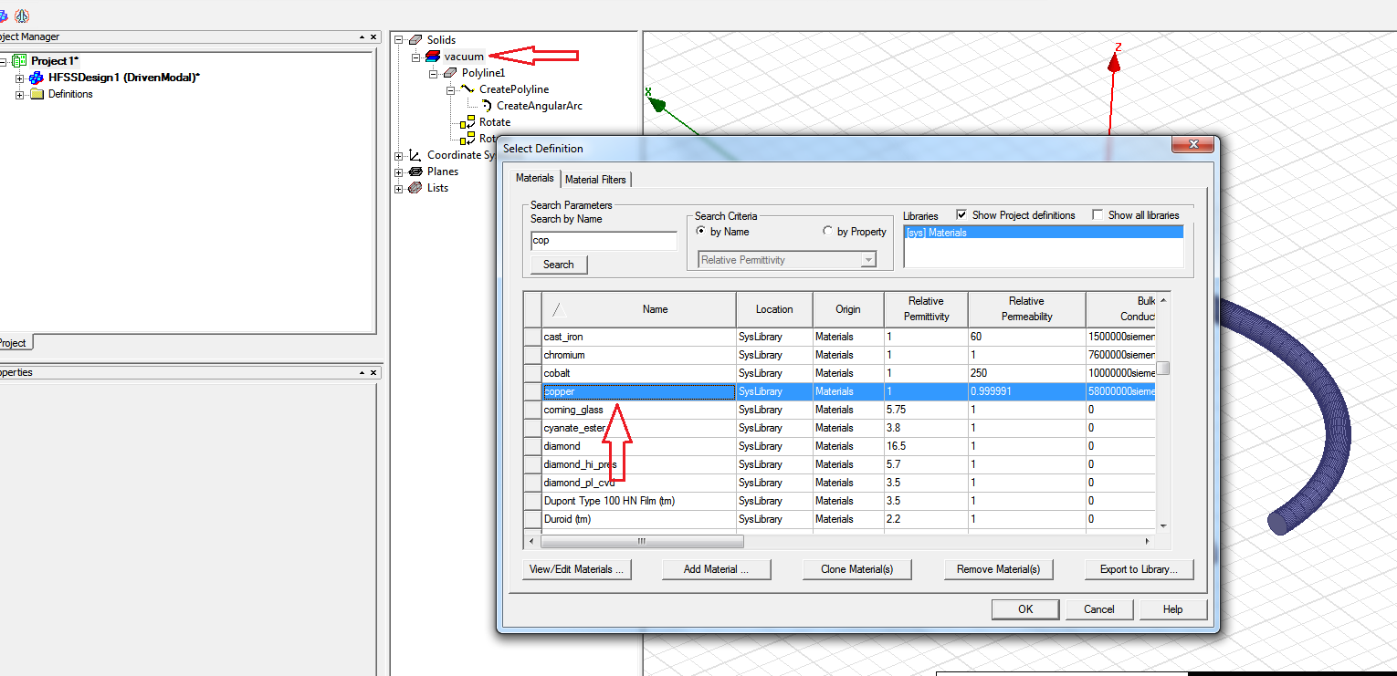
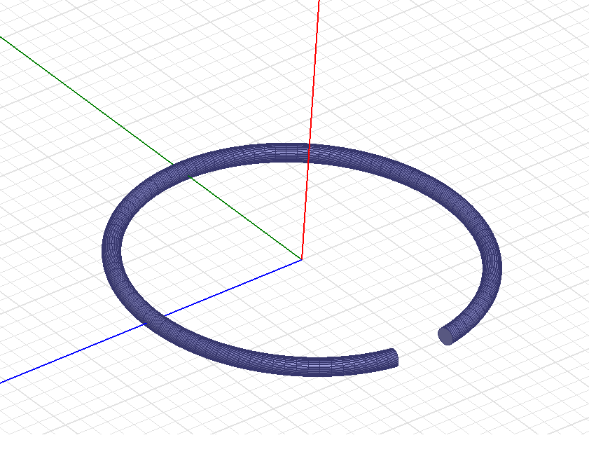
Here you can change angle:
A torus works. A circle rotated about an axis works. The rotated circle can have some interesting effects if you make the angle of rotation a parameter and then pick the wrong angle. Keep an eye on the resulting model.
