WPT Transfer Symulation HFSS
My name is Filip and I am currently working on my capstone project which is a design of a wireless charger. I was assigned to work on the computer simulation using ANSYS HFSS. Unfortunately I am not familiar with the software at all and despite hours I spent trying to figure out a lot of things, I didn't succeed. As the result I decided to create a thread where I could ask questions and hopefully get some suggestions on each stage of my work.
As of right now, I am comfortable with creating different shapes of 3D models and have some idea about analysis set up etc.
I decided to solve my problem by splitting it into few smaller stages (since simulating the final design will take forever, I want to make sure everything is set up properly instead of wasting few hours at the time).
1st stage- creating a singular helical coil and calculating its inductance as well as observing how radius change influences inductance value.
I was able to made a 3D model of mentioned coil, however I don't know how to apply excitation to my structure?
I tried applying lumped port on both sides of the polygon helix, but it doesn't work. "All the faces selected from a port source must lie on the same plane. What would be y'alls suggestion?
PS. I am using HFSS 15.0 and that's the simple design I started with:
Regards,
FiflakPL
There is a difference between energy transfer via:
(a) magnetic coupling of inductors
versus
(b) one inductor emits photons, the other receives.
HFSS is a frequent topic here. I can only suggest you try a forum search on keywords, or, click on related threads listed at the bottom of this column.
Thank you BradtheRad.
I am trying to work with magnetic coupling of inductors.
I tried digging through this forum and found some tutorials, etc however usually questions and suggestions I found are very particular for the problems people are facing. As the result, I couldn't really use too many of those hints for my purpose. I decided that since I am not going anywhere, it might be useful to just create my own thread and go from there. Thanks for your input though!
FiflakPL
How are you going to excite the coil in real life? If it's with a TEM mode, then you'd best bring the two ends of the coil together (in parallel), and use a waveport to excite them.
Howdy,
I will be feeding my coil with the voltage coming from the wall socket, converted by power-electronic designed by my teammate. However, my goal for now is to be able to calculate the inductance on the coil. As the result, whatever works will be good enough to begin with.
Regards,
FiflakPL
you should use a lumped port. on a single port model, you can simply get the inductance from im(z11)/2pif. make the airbox around at least 3 times the inductor size. if you make driven terminaldesign, you cna specify the voltage level at the port.
Hello Filip!
I am also working in the wireless power transfer area and HFSS is the primary software I use to simulate.
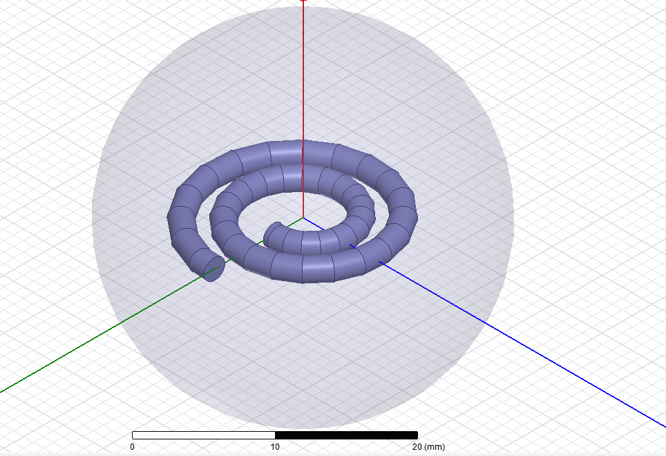
Here is a picture of a planar spiral inductor that I built in HFSS. Perhaps you could use a similar method to excite your coil.

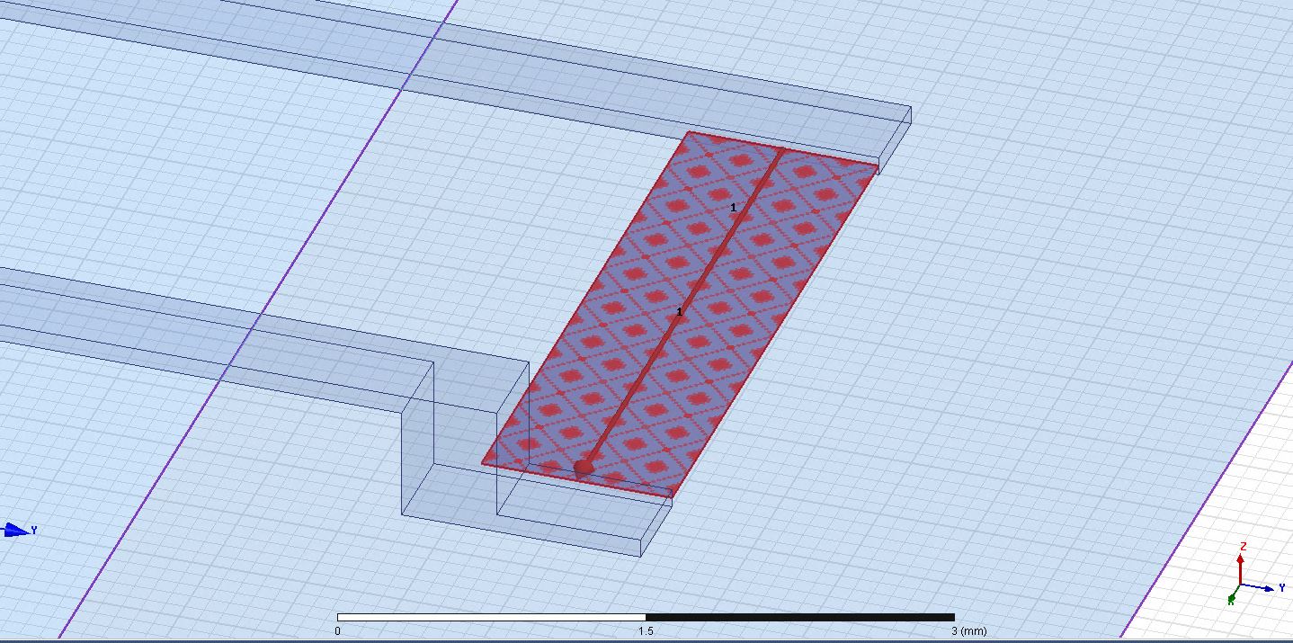
Here is a close up on the lumped port used for excitation.
If you're looking into transmitting power over a larger distance than 1 - 2cm, I highly suggest reading a paper called "A Study of Loosely Coupled Coils for Wireless Power Transfer" by C. J. Chen. Their paper has helped my research tremendously.
I hope this has been helpful!