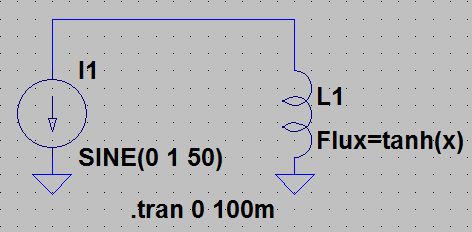
Inductor simulation in LTspice
Anybody know how to do a saturable inductor in LTspice?
I would think there would be an inductor type component somewhere in LTspice which has dialog entries for inductance at current zero amps, then inductance at current x2 amps, then inductance at current x3 amps.
This would allow you to have an inductor which was a constant vale from zero to x2 amps?.then its inductance falls linearly from x2 amps to x3 amps.
Does such a component exist in LTspice?
hi treez,
If you are a member of the LTS Yahoo group, you could check this link.
https://groups.yahoo.com/neo/groups/...ted%20inductor
https://xa.yimg.com/df/LTspice/satur...&type=download
E
Did you review the Ltspice help file about the available two non-linear inductor models?
The first (behavioral) model with a table expression for the flux does exactly what you want (piecewise linear current dependent inductance).
To model core losses along with non-linear inductance, you'll choose the hysteric core model.
Thanks, i saw that, but where in the behavioural model of the inductor are you supposed to paste the following...
I apreciate that "control right-clicking" the inductor gives the "component attribute editor", but where in that do you paste the above?
Also, i cannot see where you enter the inductances at the different current values.
Thanks, ive signed up for yahoo groups, but havent received the email confirmation. (on two occasions), so i cant get in to it.
The behavorial expression Flux = f(x) replaces the inductance value.

Hello,
I wish to have a saturating inductor in the LTspice simulation as shown in the attached pdf and LTspice simulation.
I wish the inductor value to be 100uH when its current is anywhere between zero amps and 2 amps??..then above 2 amps I wish to have its inductance fall linearly down to 1uH at 20 amps.
However, I do not believe the attached actually does that?
(The reason is to examine the high voltage that afflicts the primary DC bus capacitance when offline PFC Flyback (LED driver) converters are on no load??..and thus when the triac fires at mains peak the LC ringing can result in overvoltages on the primary DC bus)
Certainly not because the below expression doesn't describe a current dependency at all, missing x.
Flux =100u * tanh(2)
I previously suggested to use a table for the behavioral flux expression. That's possible, but unfortunately it doesn't give continuous L = f(I). To achieve this, the flux expression must not only be continuous but also continuously differentiable. tanh() and similar analytical functions are.
Thanks, i undestand the tanh function, but dont see what its use is here in making the inductance reduce as current increases.
Even if i put "x" in there it doesnt seem to help.
I can see that tanh(x) tops out at value 1, and that means you can use it to give the maximum of the saturation flux (ie getting a point where flux is not going higher as magnetising force increases)......but how that goes into the inductor "component attribute box" is not clear to me?
Inductor simulation LTspice 相关文章:
- how to maesure secondary inductor value of Transformer in cst
- Is core loss in an inductor proportional to it's inductance value?
- dc resistance of EM simulated inductor
- Power Inductor frequency characteristics calculation
- ADS Spiral Inductor on Silicon Example - Inductance Calculation Problem
- Spiral inductor simulation
