眼图问题~~~~
请问这个眼图是怎么回事,为什么中间本来的两条直线会断开?
多谢啦!
周期没取对吧
周期没错~
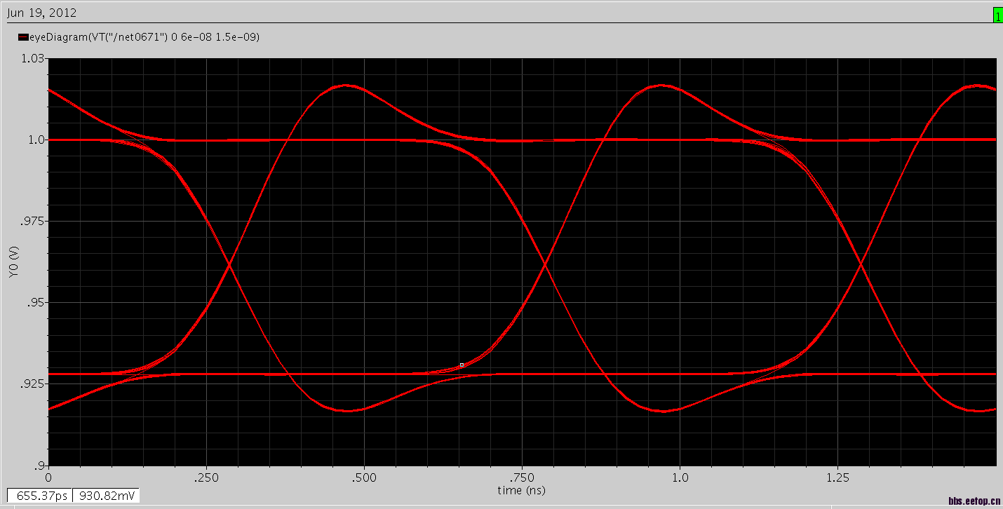
Cycle is right. Also Eye-Diagram is right. Since you do not have any jitter & noise eye diagram lines are clearly visible so there is no continuity, if noise and jitter were there there you will see all lines as continuous. Also your rise and fall times are long so when 100 pattern starts to go towards zero and 110 pattern start to go towards one there is a gap of (rise time+fall time)/2 between the two one levels and between two zero levels whose gaps are what they should be.
There are 4 pattern to run
011, 100, 110 and 001
at the end these patterns are create an eye diagram when drawn on top of each other (these patterns are clearly visible).
Reduce rise, fall times and add noise and some jitter than you will see what is seen, as in real life,on a scope screen.
周期是正确的。眼图是正确的。既然你没有任何抖动和噪声的眼图线都清晰可见,所以是没有连续性,如果有噪声和抖动,你会看到作为连续的所有行。 另外你的上升和下降时间很长,所以当100模式开始向零110格局开始朝着一个是有差距(上升时间+下降时间)/2之间的两个层次和两个零之间水平的差距,应该是什么。
有4种模式运行
011,100,110和001
在结束这些模式是创建一个眼图时,对方(这些图案都清晰可见)上绘制。
减少的上升,下降时间和增加噪声和比你会看到什么范围屏幕上,在现实生活中,看到一些抖动。
为什么上一个回答有中英文对照,而且像是机器生成的?难道现在机器人技术已经这么发达了?
学野了~!
他这个问题是取得周期太少了
While I am trying to say the same thing as you do, I am trying to say there is everything OK with above eye-diagram and trying to give reason for it.If cycles are many some jitter would be introduced is not it ? Though in simulation circuits are relatively perfect so jitter would be not much, it is better to introduce a realistic jitter (introduce noise in the VDD & GND rails etc). In ideal simulation conditions jitter would be much smaller (ideally no jitter regardless of number of cycles) than a real chip on a board produces. Unless some means of additive hitter signal is introduces given the limitation of cycles simulations always will result minimal jitter baring the eye-diagram as above.
虽然我想说的为你做同样的事情,我想说的一切与上述眼图,并试图给它的原因有确定的。如果周期是多了一些将被引入的抖动是不是?虽然在模拟电路中是比较完美的,所以抖动将是没有多少,这是更好地引进一个现实的抖动(在VDD和GND轨等引入的噪声)。在理想的模拟条件下的抖动会小得多(理想无抖动,无论周期数),比上板真正的芯片生产。除非一些添加剂安打信号的方法介绍给定的周期模拟的限制总是会导致轻微的抖动,上面露出的眼图。
你的数据时钟周期不应该是1ns吗?为什么在eyediagram中最后一项取的是1.5n呢
周期是0.5n我取的是三个眼睛1.5n的时间
感觉还是数据01顺序的安排问题
比较感兴趣的是0.075V,2GHz频率的波形,是哪方面应用?
上下边的抖动是不是和噪声有关啊
请问一下眼图里面的数据流是指?
不是很懂,先mark一下