基准的psrr曲线,怎么提高“带宽”
 红色部分的宽度怎样才能增加?
先要搞清楚psrr曲线是怎么来的,再来看如何提高,代价是什么
公式写出来就看出来了,主要应该是靠增加环路带宽吧
公式推不出来。 里面的环多,已经转晕,用了电流镜做前端调整的那种基准。 带宽提高了之后好像低频的psrr都是下降了的。没公式不懂原理
yong Cascode
提高低频psrr? 竖着的那几个管子我是改成了共源共栅了的 m1 2 3 4。
提高低频psr的话,前端调整的电流镜加了个运放试了一下, 好难调就放弃了
提高GBW;增加LPF;加LDO。
低频 你希望做到什么样的?
-120dB以上?
实用的产品能-80~-100dB就足够了,高了实际意义也不大!
高频处可以考虑-40~-60dB 这个有点难度
Useful ways to increase psrr:
1. DC PSRR: Simple techniques like cascoding , increasing channel length etc.
2. AC PSRR: for LDO try inserting buffer between pass tran and error amp, will increase UGB and hence increase PSRR, but stability is a problem for this architecture.
Other techniques include inserting a subtractor between stag1 and stage2.This will give you around 50dB at 1M makes the system also stable, simple to implement.
请问 第二种方法 加入 subtractor 具体怎么实现?
Subtractor meaning:Between stage1 and pmos output pass transistor, insert a common source stage with diode connected load. Ensure that gain of this stage is slightly less than 1 (gm1/gm2)<1 ). The diode connected pmos will replicate the supply noise on the pass transistors gate and hence PSRR will be better. Use an external capacitor to compensate the LDO.Try and let me know if you see any issues.
增加功耗
Agree with extra power dissipation , but this seems to be the best way since it only increases in proportion to the load. With the standard LDO architecture you will need to burn not less than 300uA in the second stage (pmos pass stage) to achieve 30dB at 1Mhz and still be stable.If you use other architectures such as using an amplifier to cancel out the noise on the gate,it would work only for a specific range of load currents and even this method consumes not less than 70u-80u extra current.
顶一顶 试一试
这是现在的psr
12楼的方法是不是增加运放的带宽? lpf是什么。 电容吗?
密切关注这个问题
楼上的图是到多少hz了啊,看不到啊
图不清楚 尺度看不出来
这个有论文嘛?上传一个吧,感谢ing
横线那里是80, 横坐标一大格0, 10, 100,1000,10k。
LPF is low pass filter.
12# caxias
刚刚试了,一个二极管连接的p管的gm是76u,下面的n管是70u。 最后的psrr曲线,低频63db,110kHz60db,1MHZ44db。比之前差一些。 因为这个基准的环有点多,插入这个电路之后,好几个重要管子的尺寸都有较大变化,感觉没法验证这个方法。 也许用结构再简单一点的基准来验证才行。 这边不方便,没法直接上图。还需要慢慢修改尺寸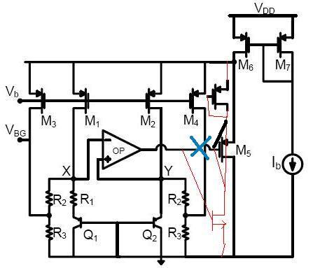
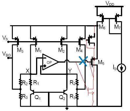
这个是修改示意图,运放输出接新的n管,上面是2级管连接的p管。原来运放到M5栅极断开。 二极管连接的pmos的源极接的不是电源,是前端调整
论坛上的ieee 基准论文合集包中有一个论文提到过,推导过分简略,而且没有频域分析。这里 上传不了
就是这个lz的图。 http://bbs.eetop.cn/viewthread.php?tid=419525&highlight=%BB%F9%D7%BC%2B
seeing
lz这个图是哪个论文上的, 能贴上来吗?论文或者论文名字
加大cap
小编已经非常不幸地成功转方向,表示模拟电路资料已经没了
低频下40 50db也就够了
恭喜恭喜现在做什么
LDO INFINEONDATASHEET