产生snr vs input amplitude(dbfs)图 疑问
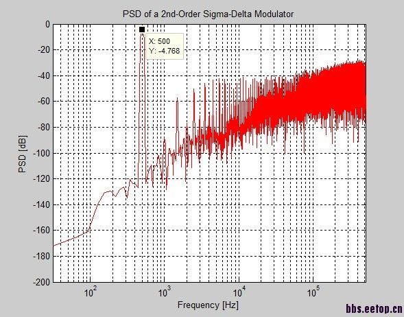 图中Y轴的值如何理解
for Ampl=0.1:0.05:Vref
Vzero=zeros(1,8);
t0=clock;
fd=1;
yy1=zeros(1,N);
open_system('ONE_PATH')
options=simset('InitialState', zeros(1,5), 'RelTol', 1e-3, 'MaxStep', 2*Ts);
sim('ONE_PATH', (N+Ntransient)/Fs, options);
%**************************************************************************************%
%**************Calculates SNR and PSD of the bit-stream and of the signal**************%
%**************************************************************************************%
yy1=Output(2+Ntransient:1+N+Ntransient)';
ptot=zeros(1,N);
[snr,ptot,psigdB,pnoisedB]=calcSNR(yy1(1:N),f,fBL,fBH,w,N);
Rbit=(snr-1.76)/6.02;
s1=sprintf('SNR(dB)=%1.3f',snr);
s2=sprintf('Simulation time =%1.3f min',etime(clock,t0)/60);
disp(s1)
disp(s2)
VrefOUT=[VrefOUT;Vref];
SNROUT=[SNROUT;snr];
AmplOUT=[AmplOUT;Ampl];
Vref
end
end
ALLOUT=[VrefOUT,AmplOUT,SNROUT];
csvwrite('outputdata',ALLOUT);
ALLOUT
请问全差分输入2.5+1,2.5+(-1)的sin信号 vref 0,5 dbfs 是怎么算的,
看你电路的fullscale是多少,输入信号除掉这个值就行了。
简单的说就是2.5+2.5, 2.5-2.5的最大sin wave会对应到0dbfs
其馀的以此类推