Problems when simulating a simple analog integrator in Pspice
Hi everyone!
Sorry that I can not type Chinese right now......
I am now trying to simulate the transient behavior of a conventional analog integrator in Pspice.
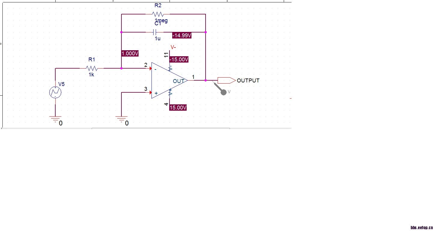
The circuit is simple, capacitor in the negative feedback loop around the ideal opamp. I attach the screenshot of the schematic.
I use a DC source as the input of the integrator. I just want to see the output of the opamp integrating with the constant.
BUT, the simulation result is very disappointing. The output of the opamp is clipped at the negative power supply. But what we expect is a ramp.
Is this result caused by the algorithm used by Pspice? There shouldn't be anything wrong with the circuit because it is too simple. I think it must have something to do with the method that pspice uses to solve the circuit.
The DC operating point simulation showed that, the voltage of inverting input terminal is not near ground. It is equal to the input voltage......too bad....
This should be something related to how Pspice extracts the matrix of the circuit, I think. But I really do not know why...
Please help! Thanks a lot!
schematic

OP simulation
你给输入一个阶跃信号吧,如果直接给DC电压,则仿真器认为C是开路的,所以就是一个反相比较器,输出时负电源应该是正常的,
I have tried to use a step input, but the transient simulation was still too bad...... far from the expected one... It seems that Pspice can not extracted the circuit matrix the same way we usually use to calculate the output...
你把瞬态响应的输出截图给我看一下吧,还有你仿真的时候最好给电容并联一个大的电阻,以设置DC工作点,一般情况下积分电路要工作,运放的反相输入端虚地要满足,所以反相输入端的DC工作点也要设置在0V,你再试试看。
Hi xjqxjq28007 ! Thanks for your help.The behavior is still far from the theoretical result...
I have just attached a operating point simulation screenshot, where I put a big resistor in parallel with the capacitor. The problem is that the negative input terminal is not virtual ground. How could I make it around ground potential? Thanks!
你自己多调整试试吧,一般情况下做瞬态仿真的时候DC工作点稳定就可以了,不一定要准确到零,但是瞬态仿真的时候正向和反向输入端的电平关系是可以看到的,我通过分析应该可以对应起来的,另外,软件只要能跑起来就不要轻易怀疑其算法,这种基本的计算我想还是可以应付的。
你在仿真的时候记得给电容设置一个初始值,一般设置为0,我仿真的结果是当输入直流电平大于0的时候(如1V),输出时线性减小的;当输入直流电平小于0的时候(如-1V),输出时线性增加的。
Hi, 谢谢你的回答!确实,在瞬态仿真的时候,初始条件必须得小心的设置,我们需要让这个电路在瞬态仿真的时候可以顺利的启动!
给你一个链接,http://www.edaboard.com/thread219027.html
这是我在国外论坛上面发同样的问题,希望他们的解答能给你帮助!
谢谢,互相帮助,
Pspice里面的理想运放是不需要直流偏置的吧,直接加小信号源就可以了。
你的工作点的反馈有问题呀,无法保证虚地,典型的放大过多,导致CLIP。
Thanking you in anticipation.