CC3200量产烧录
Hi TI员工:
关于CC3200量产烧录能不能不要像用UinFlash那样先格式化再烧录服务包然后再烧录BIN文件,这样生产效率太低了。有没有更好的方法?
我看到一个帖子上说“用一个gang programming tool去产生flash二进制image”,请问这个gang progranning tool 可以在哪里下载?有没有具体点的教程?
是不是UniFlash里的Gang Programming?我试过做一个Image,但是没有成功烧录bin文件进去,请问这个Image具体要怎么做的?
谢谢!
可以参考CC3200 Production Line Guide
- 3 Programming Using a Gang Image
Production Line Overview
Texas Instruments provides a number of resources to assist manufacturers using CC3200 devices produce products quickly and efficiently. From the beginning phases of designing products using these devices, reference design collateral and application notes are available to assist in schematic level design. This includes information about any considerations manufacturers should make in their designs to facilitate efficient manufacturing. During PCB layout development, layout guidelines are given as well. Software and hardware tools have been developed for programming and testing CC3200 devices in the production line. In addition, Over-The-Air programming functionality allows for products to have their software updated periodically even after they have been deployed.
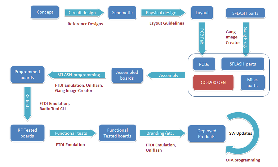
Programming the CC3200 QFN in the Production Line
Production with CC3200 devices requires files to be written to the attached serial flash device for proper operation. At the minimum, this includes the service pack that contains necessary software updates and additional features. The host program which runs on the internal Cortex M4 is stored on the serial flash also. Configuration files may also be written, which provide an initial configuration for the device upon startup. Security certificates and other content such as webpages, images, scripts, etc. can be included as well. Although most of this content is usually written during production, all content including the host program and the service pack can be continuously updated over the lifetime of the product. There are 3 basic methods of loading content onto the CC3200 serial flash:
- Uniflash - A PC based utility can be used for programming the serial flash.
- Gang image – Use a special binary image that is written directly to the serial flash, that the CC3200 can use to create the desired contents of the serial flash.
- Over-the-Air Programming (OTA) - Serial flash content can be downloaded through a network connection.
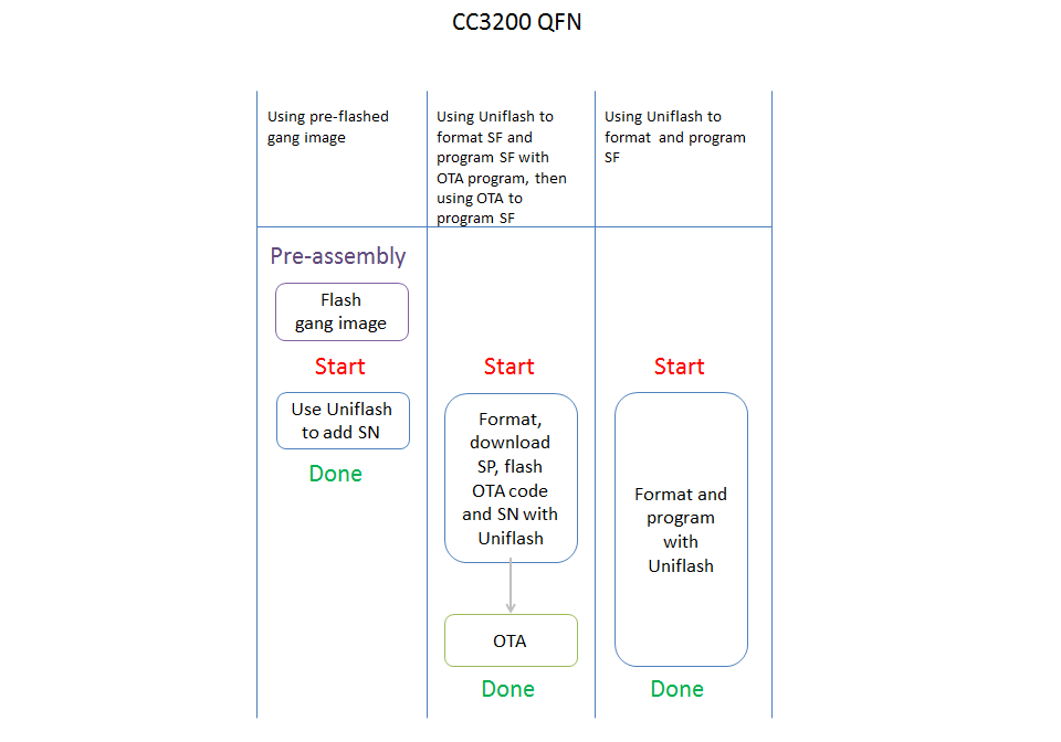
All CC3200 QFNs must have their attached serial flash devices formatted with the SimpleLink file system before files can be written. There are a number of ways to accomplish this:
- Uniflash - Make a PC connection to the CC3200 UART, and use the Uniflash utility to send a format command to the device
- Gang image - Flash a gang image to the serial flash. Have the serial flash vendor pre-program the serial flash parts with the gang image. The gang image can include a command that instructs the CC3200 to format the serial flash upon the next boot of the device.
After the serial flash has been formatted there are a couple of options to load files onto the serial flash:
- Use Uniflash to load files via the CC3200 UART interface. The CC3200 reads the files sent over UART, and loads them onto the serial flash.
- If a gang image has been flashed, the CC3200 converts the files in the image and saves them into the file system. Therefore, an additional step for loading files is not necessary.
After the service pack has been updated, Over-the-Air programming can be used to download content from the internet or from a local connection. If the CC3200 is flashed with a program that can do OTA programming, the entire serial flash contents can be reprogrammed using OTA programming. This will enable the downloading of content from the internet or from a local connection. This may be advantageous if using a small OTA program to load the final contents onto the serial flash.
Given the available options for formatting and loading content to the serial flash there are a couple of production line flows that are possible. Ranked roughly in order of speed are some possible production line flows shown below.
It is required to bring out the UART pins to provide a reliable backup flashing mechanism. If using headers to make the required connections to the programming interface, the manufacturer should consider using a single header assembly to accommodate the entire programming and test sequence as a cost saving measure. This would include the power supply, GND, and the lines necessary for flashing the serial flash.
Programming Using a Gang Image
Using this method can result in significant time savings in the case where a large amount of information must be written to the serial flash. The gang image is generally programmed on the serial flash device by the serial flash manufacturer, and therefore before it is assembled on the board. This will result in the fastest programming time out of any other method. To program the data to the serial flash via a gang programmer, it is necessary to first create a gang image that can be programmed on the target SFLASH devices. This creation process is generally performed once per product release in order to create the target image for the gang programmer. Upon power up, the CC3200 detects the presence of a gang image, and converts it to the target file system of the device. This conversion process is performed exclusively by the SimpleLink device and does not require any inputs from external interfaces. It does however extend the duration of the first power-up. This extra time should be considered when deciding what method to use in the initial programming of the serial flash. The amount of time required for the first boot after gang programming is primarily dependent on how long it takes to erase this image after the conversion is complete. This can be estimated by considering the size of the gang image, and the amount of time it takes for the serial flash to erase data.
Uniflash is the utility used for creating gang images, and it also has the ability to flash a gang image to the serial flash through UART. Instructions for creating and using gang images with Uniflash can be found here: CC31xx & CC32xx UniFlash#Image Creation and Programming
The gang image may be programmed to the serial flash device after assembly on the board provided some considerations are taken:
- The serial flash SPI interface pins must be brought out for physical contact with the programmer (e.g. male headers, test pads)
- The SPI lines must not be driven by any other source while programming.
- The CC3200 will be held in reset during programming to prevent contention.
Programming over UART
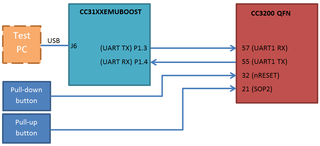
Formatting and/or writing files to the serial flash device through the CC3200 UART interface requires the use of the following CC3200 pins:
- 55 - UART1 TX
- 57 - UART1 RX
- 32 - nRESET
- 21 - SOP2
The UART TX and RX pins are used for data transfer. RTS and CTS signals are not used. The nRESET pin is used to reset the device. The UART data transfer occurs at 921600 bps. Because of this, other methods of writing files to the serial flash may takes less time.
The UART configuration is as follows:
- Baud rate: 921600
- Data bits: 8 bits
- Flow control: None
- Parity: None
- Stop bits: 1
- Polarity: Positive
The CMOS logic level specifications for the UART can be found in the CC3200 datasheet under Electrical Characteristics: http://www.ti.com/lit/ds/symlink/cc3200.pdf
Programming Using Uniflash
Using the Uniflash CLI
The Uniflash utility is PC software which can perform the following operations on the CC3200:
- Format the serial flash
- Add or remove files on the serial flash
- Update the service pack
These operations are accomplished by communicating with the CC3200 via UART. Therefore, it is necessary to supply Uniflash with a COM port number for the USB to CC3200 UART connection. See the chapter Programming over UART for details on the UART connection. Uniflash contains a command line interface which can be used in batch files/scripts for the purposes of programming the CC3200 devices in the production line. With a single line command, Uniflash can format the serial flash, update the service pack, and add any number of files. For example:
uniflashCLI.bat -config "C:\ti\uniflash_3.2\cc3xxx\sessions\uniflash_template\oob.ucf" -setOptions com=50 secure=false spPath="C:\servicepack.bin" -operations format servicePackUpdate program
When Uniflash begins, it will prompt the user to restart the device. This is so it can synchronize with the CC3200 and begin the flashing process. At this point the CC3200 must be reset by pulling down the nRESET line. When the nRESET line resumes a logic high state, the flashing procedure will begin. In the production line this reset process can be realized by using a button or other mechanism which temporarily connects the line to GND. The SOP2 pin must be pulled up during the reset. Refer to the Uniflash Wiki for complete information on how to use Uniflash.
UART Hardware Connection Using the FTDI emulation board
The CC31XXEMUBOOST can provide the required USB to UART interface for formatting and programming the serial flash via UART. The PC drivers for this board are included in the CC3100 SDK, and they should be installed during installation of the SDK. The CC31XXEMUBOOST is connected via USB from socket J6 to the PC. The jumpers on the CC31XXEMUBOOST should be connected as shown below.
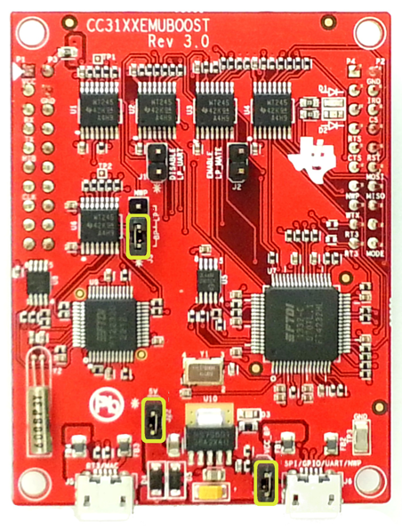
The CC31XXEMUBOOST uses a logic level of 3.3 V by default, but there are level shifters on the CC31XXEMUBOOST and it can be powered in-dependently with a different IO voltage. This can be accomplished by removing the jumper from J4, and applying the external power to pin 1 of jumper J4. On the product being programmed, the relevant CC3200 pins must be brought out for physical contact with the programmer (e.g. male headers, test pads), and must be driven by no other source while programming. The nRESET pin must be able to be temporarily pulled to GND during a reset which occurs at the beginning of Uniflash flashing procedure. The pulling down of this line can be enabled by the addition of a button or something similar to the test jig. Similarly the SOP2 pin must be able to be pulled up during the flashing procedure. The SOP2 pin must be pulled up during the device reset in order for the CC3200 to enter a mode for communicating with Uniflash.

Over the Air Programming
The CC3200 has the capability for Over-the-Air programming which allows for files to be written and updated over a network connection. An OTA programming library is available in the CC3200 SDK. The OTA update scheme relies on a subroutine that periodically checks with a remote OTA server to see if there are any available file updates. The OTA server will respond to such requests with a list of resources to update, and will also respond to requests for locations of those resources on the internet. The OTA client that runs on the MCU will download the listed resources from the locations specified by the OTA server. In the field, the resources will typically reside on a Content Delivery Network (CDN). The MCU can test the validity of the files before committing them. The committing of the new version of the file causes it to be used in place of the old one already stored in serial flash.
Using OTA in the production line can enable faster data transfer over other methods. For using OTA in the production line, a PC on the local network can run the OTA server, and can also run the content delivery server for the resources as well. The service pack should be updated before doing OTA or using any wireless functionality. For the fastest transfer of data using OTA, it is recommended to minimize RF congestion in the production environment. The OTA User’s Guide can be found in the CC3200 SDK folder at docs/CC3200 Simplelink OTA Extlib API User's Guide.chm.
Production Line RF Testing
Testing of hardware and software functionality is highly specific to each product, but there are some tools Texas Instruments has made available to assist with testing RF performance. The CC3200 can be instructed to perform RF testing operations in a number of ways:
- The CC3200 program may have a built in subroutine that is dedicated to RF testing. This could be run once upon first power-up, or could be triggered using a special external command.
- A script using the Radio Tool CLI could control the CC3200 from a PC. This would require the CC3200 to be connected to the PC through a UART to USB connection, and for a special Radio Tool program to be loaded as the MCU application
- The CC3200 could be controlled by interfacing with a dedicated RF tester.
Testing Software options
MCU Controlled RF Testing
SimpleLink API functions are available that can put the CC3200 device into modes used for RF testing. This allows for:
- Transmission of packets at specified channels, modulations, etc.
- Receipt of packets while gathering statistics for RSSI, modulation, etc.
- Carrier wave transmission
See the Transceiver Mode page for information on how to use these features. For comprehensive information about the SimpleLink API, see the Programmer’s Guide in the CC3100 SDK at: docs\simplelink_api\programmers_guide.html.
The Radio Tool library provides a set of convenience functions for RF testing:
- RadioToolOpen() - Initializes the device in preparation for RF testing
- RadioToolClose() - Stops the device
- RadioStartTX() - Transmit packets
- RadioStopTX() - Stop transmission
- RadioStartRX() - Start receiver
- RadioStopRX() - Stop receiver
- RadioGetStats() - Get statistics regarding received packets
- RadioGetMacAddr() - Retrieve MAC address of device
- RadioGetDeviceVersion() - Retrieve device Firmware version numbers
Refer to the Radio Tool wiki page for Radio Tool library source code, and for information on how to incorporate RF testing functionality into an MCU application.
PC Controlled RF Testing
Radio Tool CLI
The Radio Tool command line interface is a PC based tool that can be used to perform RF tests on CC3200/CC3100 devices. Generally, it will be incorporated into in scripts or batch files used for production line testing. When used with the CC3200, the Radio Tool CLI communicates through the UART0 (pins 55 and 57) interface of the CC3200. In order for this to work, the Radio Tool MCU application needs to be loaded as the CC3200 MCU application. This application is available in the Radio Tool package. This tool requires use of the CC31XXEMUBOOST or a CC3200-LAUNCHXL for communication between the CC3200 and the PC. Refer to the Radio Tool Wiki page for more information:http://processors.wiki.ti.com/index.php/CC31xx_%26_CC32xx_Radio_Tool
Testing with an Access Point
A straightforward method of checking for acceptable RF performance is to put the device being tested through a trial run in an RF environment with worst case conditions. Such a trial run would begin with the device under test connecting to an access point, and then communicating with either a PC on the local network or with a remote cloud server. The communication between the device under test and its peer can be monitored for reliability and speed. In order to get consistent and relevant results for all devices being tested, some actions may be taken with respect to the controlling RF environment for this type of testing:
- Minimize unintentional RF congestion in the test area. This can be accomplished by turning off other nearby 2.4 GHz band devices, and/or performing the testing in an RF shielded enclosure.
- Introduce controlled RF congestion. This can involve something such as having another device connected to the same access point, which transmits a steady stream of packets to the access point.
- Introduce attenuation in the antenna path for the access point, or place at a distance from the device being tested.
- Set the access point to communicate only on a specific channel, modulation, etc.
Board to Board RF Testing
For performing RF tests, it is possible to use one CC3100/CC3200 device to test the RF performance of another. One CC3100/CC3200 device in this case will be designated as a “golden device”: where the device is proven to have good RF characteristics, and will be used to measure the performance of devices under test. These devices would generally put into modes allowing for direct control of TX parameters, and measurement of RX statistics. This can be accomplished through using the Radio Tool CLI, the Radio Tool library, or the SimpleLink API directly. Due to limitations in the FTDI driver, 2 computers must be used to do board to board testing if using the Radio Tool for both the DUT and the golden device. One computer will control the golden device, and the other will control the DUT.
Synchronization between the DUT and the golden device may be achieved by having them communicate through a different channel of communication (other than Wi-Fi), or by using an algorithm similar to the following:
DUT algorithm:
   1. Send packets to Golden board for 4 seconds
   2. Start receiver
   3. Wait 4 seconds
   4. Measure PER and/or RSSI of received packets
   5. Stop receiver
   6. If PER and/or RSSI is acceptable
         Return success
      else
         Return failure
Golden board algorithm:
   1. Start receiver
   2. Wait 2 seconds
   3. Measure PER and/or RSSI of received packets
   4. Stop receiver
   5. If >=1000 packets received, and PER and/or RSSI is acceptable
         Send packets to DUT for 4 seconds
   6. Go to 1
Note that for this algorithm, the Golden board continues its routine indefinitely so that no intervention is required for it to function with a continuous supply of DUTs. The basis of this algorithm is that receipt of packets of an acceptable quality by the Golden board will result in a reply by the Golden board with its own packets, which will then be judged for quality by the DUT.
Please note that the DUT and the golden device must be shielded from outside RF signals. This is necessary to ensure one device is reporting statistics only for packets sent from the other. This means that if performing radiated tests, both devices should be in a single shielded enclosure. If performing conducted tests, the DUT and the golden device should be in separate shielded enclosures with an attenuation system connecting them. This is because any PER measurements will be invalidated by RF leakage from the surface of one board to the other. If the DUT and the golden device synchronize with each other through a separate communication channel, steps should be taken to ensure the physical path for that channel does not carry any RF energy that would interfere with the measurements.
Dedicated Wireless Test equipment
Using dedicated wireless testing equipment can be used if RF performance measurements with a high level of accuracy are required. Typically this will also require the use of an RF probe connector (e.g. U.FL, Murata UMC) for conducted tests, but in a carefully controlled environment radiated tests could be performed as well.
Testing with Litepoint
In collaboration with Litepoint, Texas Instruments provides support of testing CC3100/CC3200 devices with Litepoint testers. The computer that is performing the testing would be connected to the Litepoint tester via an Ethernet connection and to the DUT using a UART connection. Litepoint’s console based test tool would run on the PC, and be incorporated into the production line test script. Visit www.litepoint.com for more details.
学习了!直接把二进制文件烧录到外部spi flash,然后焊接,也可以吧?
Hi Han:
谢谢!
我根据UniFlash的指引做了个Gang image,使用Image Programming烧录,但是有问题,程序没跑起来(用Program是OK的)。请帮看下问题出在哪?一下是打印log:
[09:39:17] Begin ImageProgramming operation.
[09:39:18] INFO: > Executing Operation: Connect
[09:39:18] DEBUG: waiting and clearing uart rx buffer
[09:39:20] INFO: setting break signal
[09:39:20] DEBUG: wait for ack
[09:39:20] INFO: connection succeeded
[09:39:20] INFO: getting storage list
[09:39:20] DEBUG: wait for ack
[09:39:20] INFO: > Executing Operation: Init
[09:39:20] INFO: reading version info
[09:39:20] DEBUG: wait for ack
[09:39:20] INFO: DEVICE CC3200 ES1.33
[09:39:20] INFO: reading version info
[09:39:20] DEBUG: wait for ack
[09:39:20] DEBUG: Bootloader version is 2, 1, 4, 0
[09:39:20] DEBUG: It's a CC3200 device: PG1.33 or higher
[09:39:20] DEBUG: Switch UART pinmux to APPS
[09:39:20] DEBUG: wait for ack
[09:39:20] DEBUG: wait for ack
[09:39:21] DEBUG: Switch to NWP bootloader complete
[09:39:21] INFO: reading version info
[09:39:21] DEBUG: wait for ack
[09:39:21] DEBUG: Bootloader version is 2, 0, 4, 0
[09:39:21] DEBUG: raw storage write
[09:39:21] DEBUG: wait for ack
[09:39:21] DEBUG: status request
[09:39:21] DEBUG: wait for ack
[09:39:21] DEBUG: BlockSize is 4096, number of blocks is 16
[09:39:21] DEBUG: erasing 13 blocks starting from 0
[09:39:21] DEBUG: wait for ack
[09:39:21] DEBUG: status request
[09:39:21] DEBUG: wait for ack
[09:39:21] DEBUG: wait for ack
[09:39:21] DEBUG: status request
[09:39:21] DEBUG: wait for ack
[09:39:22] DEBUG: wait for ack
[09:39:22] DEBUG: status request
[09:39:22] DEBUG: wait for ack
[09:39:22] DEBUG: wait for ack
[09:39:22] DEBUG: status request
[09:39:22] DEBUG: wait for ack
[09:39:22] DEBUG: wait for ack
[09:39:22] DEBUG: status request
[09:39:22] DEBUG: wait for ack
[09:39:22] DEBUG: wait for ack
[09:39:22] DEBUG: status request
[09:39:22] DEBUG: wait for ack
[09:39:22] DEBUG: wait for ack
[09:39:22] DEBUG: status request
[09:39:22] DEBUG: wait for ack
[09:39:22] DEBUG: wait for ack
[09:39:22] DEBUG: status request
[09:39:22] DEBUG: wait for ack
[09:39:22] DEBUG: wait for ack
[09:39:22] DEBUG: status request
[09:39:22] DEBUG: wait for ack
[09:39:22] DEBUG: wait for ack
[09:39:22] DEBUG: status request
[09:39:22] DEBUG: wait for ack
[09:39:22] DEBUG: wait for ack
[09:39:22] DEBUG: status request
[09:39:22] DEBUG: wait for ack
[09:39:22] DEBUG: wait for ack
[09:39:22] DEBUG: status request
[09:39:22] DEBUG: wait for ack
[09:39:22] DEBUG: wait for ack
[09:39:22] DEBUG: status request
[09:39:22] DEBUG: wait for ack
[09:39:22] DEBUG: wait for ack
[09:39:22] DEBUG: status request
[09:39:22] DEBUG: wait for ack
[09:39:22] DEBUG: status request
[09:39:22] DEBUG: wait for ack
[09:39:22] DEBUG: 0
[09:39:22] DEBUG: wait for ack
[09:39:23] DEBUG: wait for ack
[09:39:23] INFO: > Executing Operation: ImageProgramming
[09:39:23] INFO: Path to the gang image file: D:/ti/image_server.xml
[09:39:23] INFO: downloading Gang Image
[09:39:23] DEBUG: raw storage write
[09:39:23] DEBUG: wait for ack
[09:39:23] DEBUG: status request
[09:39:23] DEBUG: wait for ack
[09:39:23] DEBUG: BlockSize is 4096, number of blocks is 2048
[09:39:23] DEBUG: erasing 1 blocks starting from 0
[09:39:23] DEBUG: wait for ack
[09:39:23] DEBUG: status request
[09:39:23] DEBUG: wait for ack
[09:39:23] DEBUG: wait for ack
[09:39:23] DEBUG: status request
[09:39:23] DEBUG: wait for ack
[09:39:23] INFO: downloading Gang Image
[09:39:23] DEBUG: raw storage write
[09:39:23] DEBUG: wait for ack
[09:39:23] DEBUG: status request
[09:39:23] DEBUG: wait for ack
[09:39:23] DEBUG: wait for ack
[09:39:23] DEBUG: status request
[09:39:23] DEBUG: wait for ack
[09:39:24] INFO: > Executing Operation: Disconnect
[09:39:24] DEBUG: disconnecting from device . . .
[09:39:24] DEBUG: wait for ack
[09:39:24] Operation ImageProgramming returned.
你把UNIFLASH创建gang image的截图发出来看看呢?
Hi Pan:
这个是我创建的Gang Programming
创建完这个之后Export生产一个.xml文件。然后Image Programming选择刚创建的.xml文件烧录。
烧录过程:
[11:07:10] Begin ImageProgramming operation.
[11:07:11] INFO: > Executing Operation: Connect
[11:07:11] DEBUG: waiting and clearing uart rx buffer
[11:07:13] INFO: setting break signal
[11:07:13] DEBUG: wait for ack
[11:07:13] INFO: connection succeeded
[11:07:13] INFO: getting storage list
[11:07:13] DEBUG: wait for ack
[11:07:13] INFO: > Executing Operation: Init
[11:07:13] INFO: reading version info
[11:07:13] DEBUG: wait for ack
[11:07:13] INFO: DEVICE CC3200 ES1.33
[11:07:13] INFO: reading version info
[11:07:13] DEBUG: wait for ack
[11:07:13] DEBUG: Bootloader version is 2, 1, 4, 0
[11:07:13] DEBUG: It's a CC3200 device: PG1.33 or higher
[11:07:13] DEBUG: Switch UART pinmux to APPS
[11:07:13] DEBUG: wait for ack
[11:07:13] DEBUG: wait for ack
[11:07:14] DEBUG: Switch to NWP bootloader complete
[11:07:14] INFO: reading version info
[11:07:14] DEBUG: wait for ack
[11:07:14] DEBUG: Bootloader version is 2, 0, 4, 0
[11:07:14] DEBUG: raw storage write
[11:07:14] DEBUG: wait for ack
[11:07:14] DEBUG: status request
[11:07:14] DEBUG: wait for ack
[11:07:14] DEBUG: BlockSize is 4096, number of blocks is 16
[11:07:14] DEBUG: erasing 13 blocks starting from 0
[11:07:15] DEBUG: wait for ack
[11:07:15] DEBUG: status request
[11:07:15] DEBUG: wait for ack
[11:07:15] DEBUG: wait for ack
[11:07:15] DEBUG: status request
[11:07:15] DEBUG: wait for ack
[11:07:15] DEBUG: wait for ack
[11:07:15] DEBUG: status request
[11:07:15] DEBUG: wait for ack
[11:07:15] DEBUG: wait for ack
[11:07:15] DEBUG: status request
[11:07:15] DEBUG: wait for ack
[11:07:15] DEBUG: wait for ack
[11:07:15] DEBUG: status request
[11:07:15] DEBUG: wait for ack
[11:07:15] DEBUG: wait for ack
[11:07:15] DEBUG: status request
[11:07:15] DEBUG: wait for ack
[11:07:15] DEBUG: wait for ack
[11:07:15] DEBUG: status request
[11:07:15] DEBUG: wait for ack
[11:07:15] DEBUG: wait for ack
[11:07:15] DEBUG: status request
[11:07:15] DEBUG: wait for ack
[11:07:15] DEBUG: wait for ack
[11:07:15] DEBUG: status request
[11:07:15] DEBUG: wait for ack
[11:07:16] DEBUG: wait for ack
[11:07:16] DEBUG: status request
[11:07:16] DEBUG: wait for ack
[11:07:16] DEBUG: wait for ack
[11:07:16] DEBUG: status request
[11:07:16] DEBUG: wait for ack
[11:07:16] DEBUG: wait for ack
[11:07:16] DEBUG: status request
[11:07:16] DEBUG: wait for ack
[11:07:16] DEBUG: wait for ack
[11:07:16] DEBUG: status request
[11:07:16] DEBUG: wait for ack
[11:07:16] DEBUG: wait for ack
[11:07:16] DEBUG: status request
[11:07:16] DEBUG: wait for ack
[11:07:16] DEBUG: status request
[11:07:16] DEBUG: wait for ack
[11:07:16] DEBUG: 0
[11:07:16] DEBUG: wait for ack
[11:07:16] DEBUG: wait for ack
[11:07:16] INFO: > Executing Operation: ImageProgramming
[11:07:16] INFO: Path to the gang image file: D:/ti/1234.xml
[11:07:16] INFO: downloading Gang Image
[11:07:16] DEBUG: raw storage write
[11:07:16] DEBUG: wait for ack
[11:07:16] DEBUG: status request
[11:07:16] DEBUG: wait for ack
[11:07:16] DEBUG: BlockSize is 4096, number of blocks is 4096
[11:07:16] DEBUG: erasing 1 blocks starting from 0
[11:07:17] DEBUG: wait for ack
[11:07:17] DEBUG: status request
[11:07:17] DEBUG: wait for ack
[11:07:17] DEBUG: wait for ack
[11:07:17] DEBUG: status request
[11:07:17] DEBUG: wait for ack
[11:07:17] INFO: downloading Gang Image
[11:07:17] DEBUG: raw storage write
[11:07:17] DEBUG: wait for ack
[11:07:17] DEBUG: status request
[11:07:17] DEBUG: wait for ack
[11:07:17] DEBUG: wait for ack
[11:07:17] DEBUG: status request
[11:07:17] DEBUG: wait for ack
[11:07:17] INFO: > Executing Operation: Disconnect
[11:07:17] DEBUG: disconnecting from device . . .
[11:07:17] DEBUG: wait for ack
[11:07:17] Operation ImageProgramming returned.
重新上电运行,发现程序并没有跑起来。请问从上面的信息能看出什么问题来吗?
这个是我创建的.xml文件内容:
<?xml version="1.0" encoding="UTF-8"?>
<Root>
<GangImageBuilder GangImageVendorVersion="verExample" StorageCapacityBytes="8388608"/>
<GangCommandsSetList>
<GangCommandsSet Description="Command set contain list of commands, this is the first(0) command set ">
<Command>
<CommandFormatStorage>
<ReservedBlocksBitmap>402653184</ReservedBlocksBitmap>
<FormatStorageFlagsList/>
</CommandFormatStorage>
</Command>
<Command>
<CommandStartLogger EnableLog="true" DeleteLogWhenNoErrors="true">
<FileSystemName>Gang.Log</FileSystemName>
<FileOpenFlagsList/>
<MaxFileSize>3000</MaxFileSize>
</CommandStartLogger>
</Command>
<Command>
<CommandWriteServicePack ServiePackVesrion="UCF_ROM">
<FileOpenFlagsList/>
<FileLocation>D:\ti\CC3100_CC3200_ServicePack_1.0.1.6-2.6.0.5\servicepack_1.0.1.6-2.6.0.5.bin</FileLocation>
</CommandWriteServicePack>
</Command>
<Command>
<CommandWriteFile FileToken="0" CertificationFileName="">
<FileSystemName>/sys/mcuing.bin</FileSystemName>
<FileOpenFlagsList>
<FileOpenFlag>FILE_OPEN_FLAG_FAILSAFE</FileOpenFlag>
</FileOpenFlagsList>
<MaxFileSize>37688</MaxFileSize>
<FileLocation>D:\ti\CC3200SDK_1.2.0\cc3200-sdk\example\httpserver\ewarm\Release\Exe\httpserver.bin</FileLocation>
</CommandWriteFile>
</Command>
</GangCommandsSet>
</GangCommandsSetList>
</Root>
可以
Hi HG:
可以是什么意思?能具体帮分析下我上面提到的问题吗?