TLV320AIC1106 hw bug?
One AIC1106 chip is used as a microphone/speaker PCM data converter. As figure.1 shows.
The works in a 13bit linear mode. With MCLK 2.048MHz and PCMSYNC 8kHz.
I use the AIC1106 output signal as a data source of IF I/Q modulator. First, I found there is a DC offset(about 750Hz ) to drive the center frequency 45MHz high. But when large signal exists, the influence is quite small. But when the audio signal mute, the DC offset influence appears significant, this cause an hundreds to kilo Hz noise when audio muted.
I check the AIC1106 dirver waveform. The MCLK and PCMSYNC waveform and the PCMSYNC and PCMOUT waveform as Figure.2 and Figure.3 shows, respectively.
The logic level and timing is correct.
As Figure.4, when large signal input exist, can not find anything wrong as the waveform shows. But when the input signal eliminated, the waveform obviously unusual. The 6th bit form LSB is always high. Different signal level input has been tested. The 6th bit has the same behavior. When signal is small enough( a very small range), the 0th bit to 5th bit (count form LSB) varies but the 6th bit keep high.
Finally, I believe the 6th bit unsual behavior causes the I/Q modulator output a wrong IF frequency with about 750Hz freq DC offset (I added a 300HPF to eliminate the mute noise( whistle).
My question is:
1. Is the application circuit correct ?
2. If the circuit is correct ( I can't find any thing wrong till now). The 6th bit unusual cause by chip bug?
3. Any software technic can avoid this?
Hope give me a reply to help me to use the AIC1106 in my project. Thanks ahead.
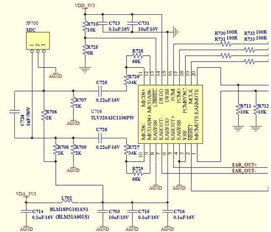
Figure.1 Main part of TLV320AIC1106 application circuit.
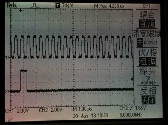
Figure.2 The MLCK and PCMSYNC waveform.
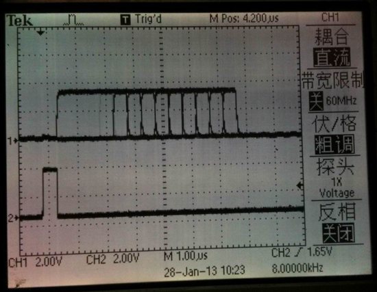
Figure.3 The PCMOUT waveform when large signal input
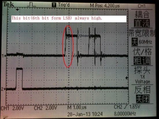
Figure.4 The PCMOUT waveform when signal off.
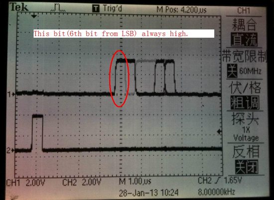
Figure.5 The PCMOUT waveform when signal off.
Hi, Yong sen,
你的问题是指PCMO输出异常吗?图4和图5都是异常的波形吗?你指的audio mute是怎么进行操作的?
谢谢!
This is typical of delta-sigma audio ADC. This is caused by the offset voltage of internal circuit. For operational amplifier, when the input is 0, the output has some small DC offset output. Just like operational amplifier, for delta-sigma audio ADC, when the input is zero, the output is not zero, but some low amplitude output.
For instrument and industrial application, this offset voltage is harmful and is restrictly controlled. For audio application, however, this low amplitude DC offset is not harmful since only AC signal above 20Hz is used.
If you still care about the DC offset signal, you can remove it by using a simple 1st order IIR high pass filter in your firmware.
Figure 4 and figure 5 are the oscilloscope waveform photos of the PCMO pin of an AIC1106 under tested. Meanwhile, the input MIC wires were shorted(no signal input) and MIC_MUTE was applied a low logic level (below 0.5V) .
As Figure.1 shows, I used two 0.22uF capacitors to avoid external DC offset. So, the DC offset of digital output can only caused by the internal circuit.
I first found a 200Hz frequency offset when I use this audio signal source as an I/Q IF modulator input (of cause after filted by 300Hz~3400Hz BPF(HPF+LPF) and orthogonal transform). I want a very precise center carrier frequency ( 1Hz at 45MHz IF), especially in the silence piece of a speech.
I use a 93-taps FIR HPF filter( 24dB@200Hz, 0.5dB@300Hz, 8000Hz sample rate, 16bit coeff). to eliminated the AIC1106 DC offset, but a 80Hz offset of center frequency still exist. I think a much more better HPF filter must be used, but I have very few MIPS budgets left for this HPF.
I think the better way is replace the AIC1106 chip with a HPF filter capable PCM-CODEC. But it's very hard to find a ultra-low power PCM-CODEC like the AIC1106.
Do you have any recommendation of substitution?
Hi Yongsen,
There should only have a small DC offset, the AC offset you mentioned looks strange and make few sense here. Can u ground analog input either AC or DC coupled, and measure this offset again. In general, you can add HPF to remove this offset, or else, user can calibrate this offset if DC performnece is cared.
Yongsen,
You are right. The DC offset is caused by internal circuit.
IIR is more source effective to remove this DC offset. in codec that has built in HPF to remove the DC offset also use IIR filter (often use one order IIR).
Best Regards
Frank Pan
