Frequency Diversity Radar
In order to overcome some of the target size fluctuations many radars use two or more different illumination frequencies. Frequency diversity typically uses two transmitters operating in tandem to illuminate the target with two separate frequencies like shown in the picture.
The received signals can be separately processed in order to maintain coherence. In addition to the 3dB gain in performance achieved by using two transmitters in parallel, the use of two separate frequencies improves the radar performance by (typically) 2.8dBs.
With the multiple frequency radar procedure it is possible to achieve a fundamentally higher maximum reach, equal probability of detection and equalfalse alarm rate. That is, if the probability of detection and the false alarm rate are equal in both systems, then by using two or more frequencies it is possible to achieve a higher maximum range. The smoothing of the fluctuation of the complex echo signal is the physical basis for this. The extreme values (minima and maxima) are moved against each other because of the differences in the secondary radiation diagram of the target for the different carrier frequencies. If the backscatter of the first frequency has a maximum, then the backscatter of the second frequency has a minimum for most part. The sum of both signals don’t alter the average of the single signals. This causes a smoothing of the resulting signal at an addition of the single received signals. The reflected single signals must be independent in order to increase the maximum range by increasing the probability of detection of the target. The disadvantage of this process is that the signals have different spectra and therefore they are easily detected, making a target visible to the enemy.
The multiple frequency procedure is used by the following technical methods:
- Simultaneous transmission of several pulses at different carrier frequency in the simplest form can be made with several transmitters and receivers working simultaneously.
- Succession following radiation of several signals the carrier frequency can be changed by changing the frequency:
- of each pulse after the other (frequency agility),
- within the duration of a single pulse (frequency diversity) and
- after several pulses (possible at higher pulse repetition frequencies only).
Combinations of several methods are also used.
Example given: the ATC-radar ASR-910 uses multiple frequencies, transmitting two pulses closely following the other (frequency diversity), and the RRP-117 air defense radar is also equipped with two frequency carriers and an additionalpulse compression. (Since the spectra of the transmitted frequencies cover themselves in the pulse compression, other rules have to be considered.)
The delayed radiation of several signals has advantages opposite to the simultaneous radiation of several signals:
- different transmitted signals don't influence each other,
- more favorable energy conditions arise from the delay, therefore there is no need of using different transmitters and
- a simple construction of the transmitters and the antenna systems.
An important advantage of the multiple frequency procedure is the high jamming immunity of the procedure. The further processing of the single received signals has a contribution to that. The linear addition of the signals of different frequency components increases the probability of detection of the target. However, this brings disadvantages with regard to the jamming immunity like a radar with a single Tx-frequency only.
The work with two transmitters of different frequencies (E.g.: ASR-910) is often looked at falsely only for reasons of the redundancy. („However, if a transmitter fails, I still have the other transmitter!”) The projected maximum range of the radar unit is then reduced to 70%1. This fact is usually noticed by the flight checker, however, the cause is usually checked somewhere else.
1) fourth root from the losses of 3dB (decreased Tx-power) plus 2 to 2,5dB increasing of the fluctuations loss
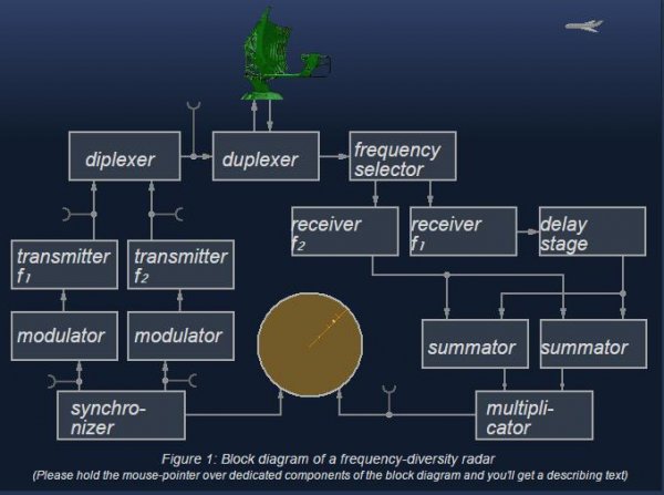
Principle of OperationSynchronizerThe synchronizer supplies the synchronizing signals that time the transmitted pulses, the indicator, and other associated circuits.
ModulatorThe oscillator tube of the transmitter is keyed by a high-power dc pulse of energy generated by this separate unit called theModulator.
TransmitterThe radar transmitter produces the short duration high-power rf pulses of energy that are radiated into space by the antenna.
CommutatorFigure 2: Commutator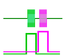
A commutator is actually a time controlled switch. The word comes from Latin and means „collecting bar” or „call handling”. Either the commutator works passively (all incoming RF pulses on the three input jacks will be conduct to the output jack) or actively (the RF input pulses are switched to the output time controlled by separate gate pulses like shown in the figure.)
Since very high frequencies must be switched very fast, the commutator uses a wiring technology like the one used by the duplexer.
DuplexerThe duplexer alternately switches the antenna between the transmitter and receiver so that only one antenna is used. This switching is necessary because the high-power pulses of the transmitter would destroy the receiver if energy was allowed to enter the receiver.
AntennaThe antenna transfers the transmitter energy to signals in space with the required distribution and efficiency. This process is identical during reception.
Frequency SelectorThe frequency selector is a frequency-separating filter. It separates the received echo-signals into the receivers depending on the frequency.
ReceiversThe receivers amlify and demodulate the received RF-signals. The receiver provides videosignals on the output.
Delay stagef2 f1 oscilloscope delay time Figure 3: delay time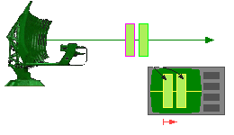
At the transmitter, pulse f2 is delayed by a predetermined time with respect to pulse f1. To undo this delay on the receiving path (The pulse f2 won't dwell faster, even if we want it!
![]() ), the pulse f1 must be delayed exactly with the same time delay. Now the signal processor can process both signals simultaneously. Notice, that the first pulse transmitted is shown on the oscilloscope as the first pulse as well, i.e. on the left side of the screen!
), the pulse f1 must be delayed exactly with the same time delay. Now the signal processor can process both signals simultaneously. Notice, that the first pulse transmitted is shown on the oscilloscope as the first pulse as well, i.e. on the left side of the screen!
The single signals are processed in parallel in separate channels at a multiple frequency radar unit. These signals arethen accumulated and compared with a threshold value. Several processing procedures are used:
- linear addition of the amplitudes of all channels (maximum range at low jamming immunity);
- multiplication of the amplitudes of all channels (maximum jamming immunity, but at the lowest value of the maximum range);
- addition of the squares of the amplitudes of all channels (optimal procedure!);
- linear addition of the amplitudes of several channels followed by a multiplication of the partial sums (This procedure is drawn in the upper functional block diagram.);
- Multiplication of the amplitudes of several channels followed by addition of the partial results.
High effectiveness is reached when using one of the mentioned processing procedures.
But which procedure to use to which radar unit is usually highly classified.
The indicator should present to the observer a continuous, easily understandable, graphic picture of the relative position of radar targets.
布局问题,图没了