汽车USB电源电路
汽车USB电源电路
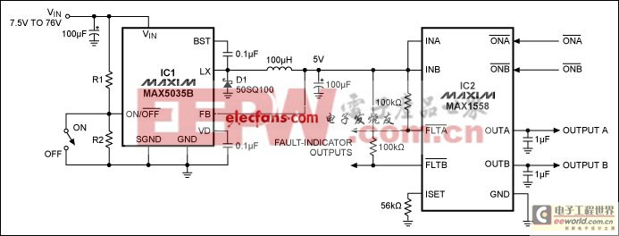
Adding a dual USB switch (MAX1558) to a switching regulator (MAX5035B) yields a small circuit that can be built into the plug of an automotive cigarette lighter. It enables the single lighter socket to power or charge two automotive accessories such as portable navigation devices, while providing fault indicators and overload protection.
Automotive accessories such as portable navigation devices (PNDs) are usually powered or charged using a simple adaptor plugged into the cigarette lighter. But, what if you want to power or charge two devices at once? The circuit in Figure 1 is just what you need.

Figure 1. This automotive USB power supply generates two regulated, supply-voltage outputs from a single unregulated input.
IC1 generates 5V from any input between 7.5V and 76V. That range is wide enough to include the complete range of car-battery voltage plus the 40V spike that can occur during a load dump. The IC is simple to use, because it has an internal power switch and requires no compensation circuit.
IC2 distributes the 5V generated by IC1 to two separate outputs. It not only distributes power, it also protects against overload conditions. Most portable equipment is powered or charged through a USB interface, whose current limit is 500mA. Because IC2 is intended for USB applications, it latches off any port that tries to deliver more than 500mA, while leaving the other port unaffected. Auto-restart capability ensures that the port recovers automatically after the overload condition has been removed.
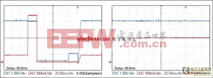
Figure 2 shows the protection feature in action. Output B has a constant load of 300mA, and output A is switched between a load of 100mA and an overload of 600mA. On the left we see that IC2 switches off output A after an overload, but allows a 20ms delay to avoid responding to brief transients. The overload is removed 80ms later, and after another 20ms the auto-restart brings output A back online. On the right, we see that output B is completely unaware of the problem in output A. (The fault indicator output FLTA, however, goes low to indicate a problem in channel A.)

Figure 2. These current/voltage waveforms from Figure 1 show that an overload on output A (left graph) has no effect on output B (right graph). Fault indicator outputs FLTA and FLTB warn of overloads.
This circuit is small because it has few external components. You can build it into a cigarette lighter plug, or place it in a small space behind the dashboard.
- 即将普及的碳化硅器件(10-19)
- 纳米技术帮助锂电池瘦身(08-20)
- 设计机顶盒的水平和垂直极化天线驱动电源(12-03)
- 智能型的铅酸蓄电池管理系统(04-29)
- PWM加相移复合控制双向DC/DC变换器优化设计(07-28)
- 基于PIC单片机的数字式智能铅酸电池充电器设计(07-29)
