LTE测试:你需要知道的那些事
er control, and receiver sensitivity, will be familiar from earlier technologies, but due to the transmission schemes used (OFDMA in the downlink, SC-FDMA in the uplink), new measurement equipment will be needed to support these tests.
Other measurements are specific to LTE. With its OFDMA transmission scheme, for example, error vector magnitude (EVM) per sub-carrier becomes an essential test of modulator performance. With the availability of the 700-MHz analog TV spectrum, LTE will be deployed at lower frequencies than GSM or WCDMA, resulting in much broader bandwidths: 20 MHz/700 MHz = 2.8%, compared with 5 MHz/2100 MHz = 0.24% for typical WCDMA devices. This can pose a challenge with some modulator architectures as it results in a higher EVM at the band edges, so it needs special attention at the design stage.
Due to the dynamic nature of some of the tests, such as power control, the measurement conditions need to be established using the signaling protocol. This makes it essential for the test equipment to include the protocol stack, simulating the evolved Node B (eNB) base station. Since these measurements are usually performed by RF engineers rather than protocol specialists, the test equipment used must be simple to configure, allowing engineers to focus on the measurement being made.
Protocol Testing
One of the main challenges for the protocol stack developer will be to ensure that the state change response requirements are met. Although the LTE specifications have reduced the number of states that a terminal can be in to RRC_IDLE and RRC_CONNECTED, the time it takes to change from one to the other
will be a major part of the latency budget when data needs to be sent.
In RRC_IDLE mode, as much as possible of the device electronics will be in a low-power consumption state to ensure good battery life, with the receiver activated periodically to check for paging messages. When data transmission is scheduled, the device must wake up and rapidly synchronize its uplink.
Protocol testing can often involve expending as much effort on generating test cases as on creating the protocol stack, so access to comprehensive and efficient test facilities is vital. In order to be able to break down the testing, it is important to be able to test each sub-layer in both the User Plane and Control Plane. Protocol test diagnostic features are essential when tracing faults. Typically, this would include time-stamped message logging and decoding. But it is important that this is available for each sub-layer, providing the ability to trace through signaling message flows in detail, from MAC PDUs up to RRC messages, thus ensuring that timing requirements are met.
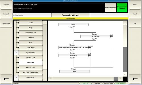
The ability to create test scenarios for each layer requires detailed control of the test equipment, but this needs to be kept as easy to use as possible to avoid a painful learning curve. Graphical test description, as provided by the Aeroflex 7100 Scenario Wizard, offers the clearest method of defining new tests (Fig. 1).

Figure 1 - The Scenario Wizard is used to generate new test procedures using a graphical, flow-chart method. These tests are built from functional blocks, e.g., "Create Cell," where the user can configure a range of parameters. The user also can create new functional blocks to extend the Scenario Wizard.
Performance Testing
Once the RF, baseband, protocol stack, and application layer have been integrated, overall device performance needs to be fully characterized. During this stage, it will be necessary to trace and eliminate bottlenecks to max
- AT4为艾法斯拓展WiMAX与协议分析市场(03-28)
- Aeroflex 3500便携式射频测试仪新增VSWR测试功能 (03-28)
- Aeroflex推出C.S 004 4-A测试套件(05-24)
- Aeroflex在其3000 Series产品中加入嵌入式PXI系统控制器(01-01)
- Aeroflex 5800系列推出数字功能,支持混合信号测试(03-10)
- Aeroflex新增的LTE TDD测试套件扩展其PXI 3000系列模块化仪器功能(03-01)
