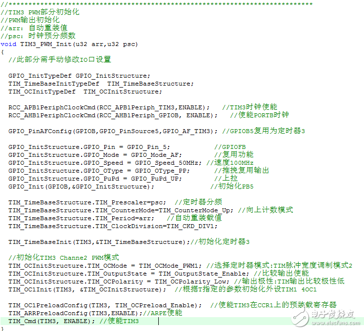
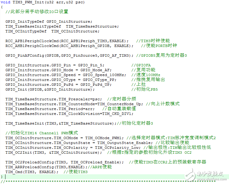
stm32F4的PWM发生器无法产生PWM信号


配合的好像不太正确,下面是F4库里的例子(或是你直接去固件库里看里程,STM32固件库手册等\STM32F4xx_DSP_StdPeriph_Lib_V1.5.1\Project\STM32F4xx_StdPeriph_Examples\TIM\TIM_7PWMOutput):
int main(void)
{
/*!< At this stage the microcontroller clock setting is already configured,
this is done through SystemInit() function which is called from startup
files (startup_stm32f40_41xxx.s/startup_stm32f427_437xx.s/startup_stm32f429_439xx.s)
before to branch to application main.
To reconfigure the default setting of SystemInit() function, refer to
system_stm32f4xx.c file
*/
/* TIM Configuration */
TIM_Config();
/* TIM1 Configuration ---------------------------------------------------
Generate 7 PWM signals with 4 different duty cycles:
TIM1 input clock (TIM1CLK) is set to 2 * APB2 clock (PCLK2), since APB2
prescaler is different from 1.
TIM1CLK = 2 * PCLK2
PCLK2 = HCLK / 2
=> TIM1CLK = 2 * (HCLK / 2) = HCLK = SystemCoreClock
TIM1CLK = SystemCoreClock, Prescaler = 0, TIM1 counter clock = SystemCoreClock
SystemCoreClock is set to 168 MHz for STM32F4xx devices
The objective is to generate 7 PWM signal at 17.57 KHz:
- TIM1_Period = (SystemCoreClock / 17570) - 1
The channel 1 and channel 1N duty cycle is set to 50%
The channel 2 and channel 2N duty cycle is set to 37.5%
The channel 3 and channel 3N duty cycle is set to 25%
The channel 4 duty cycle is set to 12.5%
The Timer pulse is calculated as follows:
- ChannelxPulse = DutyCycle * (TIM1_Period - 1) / 100
Note:
SystemCoreClock variable holds HCLK frequency and is defined in system_stm32f4xx.c file.
Each time the core clock (HCLK) changes, user had to call SystemCoreClockUpdate()
function to update SystemCoreClock variable value. Otherwise, any configuration
based on this variable will be incorrect.
----------------------------------------------------------------------- */
/* Compute the value to be set in ARR register to generate signal frequency at 17.57 Khz */
TimerPeriod = (SystemCoreClock / 17570 ) - 1;
/* Compute CCR1 value to generate a duty cycle at 50% for channel 1 and 1N */
Channel1Pulse = (uint16_t) (((uint32_t) 5 * (TimerPeriod - 1)) / 10);
/* Compute CCR2 value to generate a duty cycle at 37.5% for channel 2 and 2N */
Channel2Pulse = (uint16_t) (((uint32_t) 375 * (TimerPeriod - 1)) / 1000);
/* Compute CCR3 value to generate a duty cycle at 25% for channel 3 and 3N */
Channel3Pulse = (uint16_t) (((uint32_t) 25 * (TimerPeriod - 1)) / 100);
/* Compute CCR4 value to generate a duty cycle at 12.5% for channel 4 */
Channel4Pulse = (uint16_t) (((uint32_t) 125 * (TimerPeriod- 1)) / 1000);
/* TIM1 clock enable */
RCC_APB2PeriphClockCmd(RCC_APB2Periph_TIM1 , ENABLE);
/* Time Base configuration */
TIM_TimeBaseStructure.TIM_Prescaler = 0;
TIM_TimeBaseStructure.TIM_CounterMode = TIM_CounterMode_Up;
TIM_TimeBaseStructure.TIM_Period = TimerPeriod;
TIM_TimeBaseStructure.TIM_ClockDivision = 0;
TIM_TimeBaseStructure.TIM_RepetitionCounter = 0;
TIM_TimeBaseInit(TIM1, &TIM_TimeBaseStructure);
/* Channel 1, 2,3 and 4 Configuration in PWM mode */
TIM_OCInitStructure.TIM_OCMode = TIM_OCMode_PWM2;
TIM_OCInitStructure.TIM_OutputState = TIM_OutputState_Enable;
TIM_OCInitStructure.TIM_OutputNState = TIM_OutputNState_Enable;
TIM_OCInitStructure.TIM_Pulse = Channel1Pulse;
TIM_OCInitStructure.TIM_OCPolarity = TIM_OCPolarity_Low;
TIM_OCInitStructure.TIM_OCNPolarity = TIM_OCNPolarity_High;
TIM_OCInitStructure.TIM_OCIdleState = TIM_OCIdleState_Set;
TIM_OCInitStructure.TIM_OCNIdleState = TIM_OCIdleState_Reset;
TIM_OC1Init(TIM1, &TIM_OCInitStructure);
TIM_OCInitStructure.TIM_Pulse = Channel2Pulse;
TIM_OC2Init(TIM1, &TIM_OCInitStructure);
TIM_OCInitStructure.TIM_Pulse = Channel3Pulse;
TIM_OC3Init(TIM1, &TIM_OCInitStructure);
TIM_OCInitStructure.TIM_Pulse = Channel4Pulse;
TIM_OC4Init(TIM1, &TIM_OCInitStructure);
/* TIM1 counter enable */
TIM_Cmd(TIM1, ENABLE);
/* TIM1 Main Output Enable */
TIM_CtrlPWMOutputs(TIM1, ENABLE);
while (1)
{}
}
可以了,修改成了OC2,比较器2就有波形了。


比较器1好像是有点特别的,配置的时候比正常其他的比较器多了个函数,这个网上很多的
