How to achieve wireless connection between a resonator sensor and VNA?
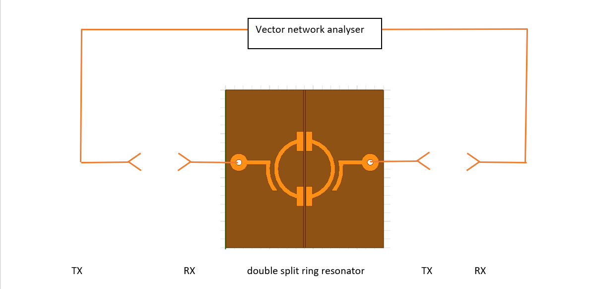
I am currently doing a project to make a wireless sensor, which should have the following structure:

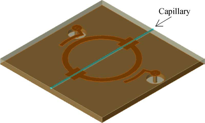
My task is to connect the double split ring resonator (DSRR) and vector network analyser (VNA) wirelessly. DSRR is a microstrip resonator whose resonant frequency shifts if liquid is introduced to flow through the capillary. Therefore, it can be used as a sensor to detect liquid.


I know there are several possible ways to achieve the wireless connection, but I am totally stuck.
I tried to use rectangular patch antenna as TX/RX antennas similar to the paper ?Wireless Sensing of Complex Dielectric Permittivity of Liquids Based on the RFID? (but the paper uses ultrawide band microstrip dipole antenna). However, I failed, my CST simulation results show no resonance.


I used cross polarization, so cross talk is not a big issue?
In addition, I guess because the DSRR does not have a distinctive peak, the overall frequency response cannot reflect the DSRR resonance.
I am not sure whether my interpretation is correct or not, can anyone help me?
Moreover, my supervisors suggest me to use antennas with higher directivity. Is there any microstrip antenna with simple structure can achieve much higher directivity?
Furthermore, is it also possible to use nfc antenna or near-field antenna for the wireless connection? But I don?t know how to realise it with microstrip at GHz. Neither don?t I know how to build the LC tank if the DSRR has inductive impedance.
Please help me out
Many thanks
Ran Tao
If you use wireless modules at input/output of this structure, you measure the impedances of the wireless modules not sensor.Calibration cannot be done..
Wirless modules are unidirectional devices so you need a reflected wave to measure the reflections but it's impossible..Transmission can be measured but I guess it will be not consistent.
Thanks for your reply.
But could you explain more about the wireless modules? Do you refer to it as the TX/RX antennas I used?
I agree that the resulting S21 affected by both the TX/RX antennas impedance as well as the sensor impedance (and antennas may have bigger contribution in my case). The impedance of a single antenna can be measured by looking at reflection loss, but the impedance of an antenna pair is more difficult to measure.
Overall, does it mean that when TX/RX antennas are added, the overall S21 cannot indicate the S21 of the sensor itself? What's worse, calibration cannot be done to exclude the impact of TX/RX antennas?
I am wondering why there are some successful examples in this field, like the paper I mentioned in my last post and the 35-bit chipless RFID transponder (https://ieeexplore.ieee.org/document/5296182)?
Thanks for your reply.
But could you explain more about the wireless module? Do you refer it to the TX/RX antennas I used?
I agree that the overall S21 is affected by both TX/RX antenna impedance as well as the sensor itself (may be the impedance of antenna has larger contribution in my case). The impedance of a single antenna can be measured by looking at the reflection loss, but the impedance of an antenna pair is more difficult to measure.
Overall, does it mean that when the TX/RX antennas are added, the overall S21 cannot indicate the S21 of the sensor? What's worse, calibration cannot be done to exclude the impact of TX/RX antennas?
I am wondering if this is true, why there are some successful examples in this field, like the paper I mentioned in my last post, and the 35-bit chipless RFID transponder (https://ieeexplore.ieee.org/document/5296182)?
Antennas are other issues.The measurement cannot be done healthy due to antennas' radiation problem.If these antennas are even very well positioned, the problem will arise due to lack of radiation inequalities of the antennas.
VNA-->Wireless_Module_1-->Antenna <Free_Space> Antenna_2-->Sensor<--Antenna_2 <Free_Space> Antenna_1<--Wireless_Module_2<--VNA
As you see the system is pretty complex and an healthy measurement is almost not possible. S21 can be measured-maybe- but Sxx no..
I see your point, but in my project, wireless modules are not needed, all I need to do is to transmit the signal from VNA via the antenna.
So the flow should be
VNA-->Antenna_1 <Free_Space> Antenna_2-->Sensor<--Antenna_3 <Free_Space> Antenna_4<--VNA
Therefore, everything is in analogue.
My problem is that why I can't get a similar S21 as the S21 of the sensor if antennas are added.
Is that because of antenna impedance or antenna radiation pattern? I forgot to say that free space between two antennas is quite small, so it is actually in near field.
Thanks
Even the antennas 100% identical, this measurement test-bench will have troubles.Positions of the antennas are very critical and they have to see each other exactly face to face that is quite difficult.
Also, reflection from other objects will disturb the measurement..It's not healthy method at all..
I guess by using near field coupling would be helpful to avoid the problems you mentioned? I am also thinking of using inductor-like microstrip antenna for near field coupling. But I don't know how to incorporate it with the resonator.
