Wireless rectenna on flexible board
I am trying to build a simple rectenna system on a flexible board to turn on an LED.
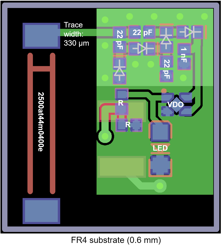
I started off with ADS simulation, followed by PCB fabrication on conventional FR4 board.
Till here, everything worked fine and the LED turned on at 2~3 meters away from the transmitting antenna.
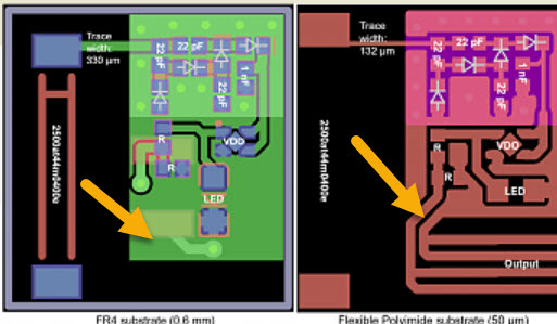
However, if I move the circuit to a flexible board (polyimide; 50um), the device has extremely poor performance. LED would only turn on at 10~20 cm away from the external antenna.
I am using a Johanson chip antenna (2500at44m0400e), murata capacitors and Skyworks silicon Schottky diodes.
Only thing I changed from the FR4 substrate is the RF trace width, which I calculated to match 50 ohm impedance (based on CPWG transmission line) on the new substrate.
Based on this, the trace width reduced from 330 um to 132 um.
Could you please recommend any solutions to this issue? Is the substrate too thin? should I try different capacitor values?
Thank you all in advance!


Your calculation of the new 50 ohms transmission line is good (from FR4 to Polyimide).
The only thing that I see is that you don't have any impedance matching components for the Johanson antenna.
If you check the datasheet of the antenna you can see that Johanson recommends to use up to 3 matching components.
I think you was just lucky in the case of the FR4 board, to get somehow the right antenna impedance, without using impedance matching network.
https://www.johansontechnology.com/d...0AT44M0400.pdf
These chip antennas are extremely sensitive to the exact PCB environment, including ground plane size.
The micro strip trace width may be correct, the trace outside the ground plane is not. You are adding considerable series inductance in the flex design.
Compared to the Johanson reference designs, the ground planes of both boards are rather small. I agree with vfone that the FR4 board works by chance.
Yes. The thing is, I initially tried impedance matching, but it turned out the matched version (on FR4) did not perform better than the unmatched one. Since I do not have a network analyzer in hand, I could only rely on ADS and could not do any real component matching. I should probably try adding matching components for the flexible board to see if that works better. Thanks!
Thank you! Do you have any other suggestions besides the chip antenna? I tried designing my own elliptical patch antenna, but it did not perform very well either. What antenna would you say is the least sensitive antenna?
Thank you for your reply. I also realized this when I was designing the board. Because the antenna feedline portion is not CPWG construction, I was wondering which calculation method is the correct choice. I searched some literature, and some say I should use microstrip and some say I should use CPW.
Do you have suggestions on the calculation method for this feedline?
On this Johanson webpage is a lot of information how to tune this kind of antenna:
http://johansontechnology.com/tuning
You have to re-design the PCB and get space for 3 matching components (Pi network, as Johanson recommends).
Without a VNA would be hard to tune it, but not impossible. Start using component values that the manufacturer recommends.
As FvM mentioned, the ground situation near the "hot" end of the antenna (largest E field) is completely different. In the flex design, you have broken that solid ground plane.

The antenna itself is not the issue - other small antennas are also sensitive to PCB size. I'm often doing EM-simulation for clients to design small antennas for small boards, and ground size is always a critical influence. There is no easy answer, such small antennas on small PCB are very sensitive, always.
As the others mentioned, prepare your design for a matching network so that you can tweak in the lab.
