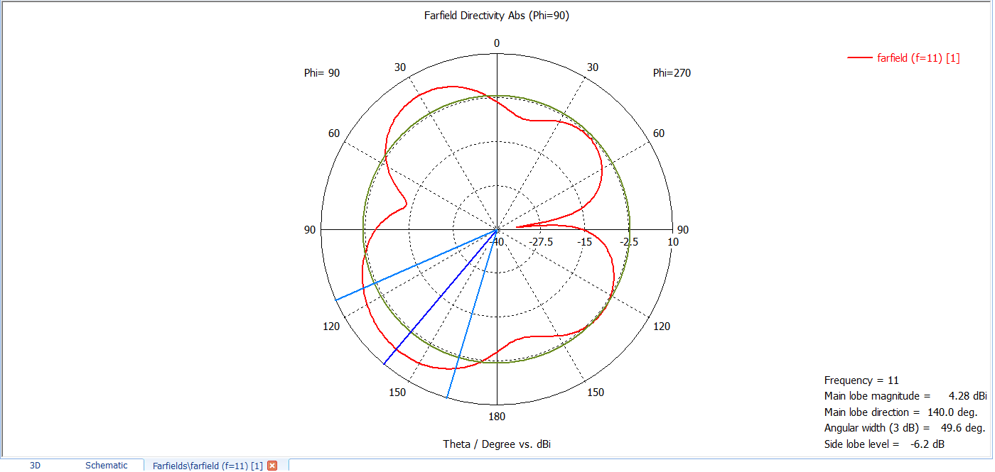
CST radiation diagram
时间:03-29
整理:3721RD
点击:
Hello everyone.
I have questions analyzing the diagram in the CST software.
The 3 blue line we have the directivity, ok?
In the circumference of red color we have the shape of the magnetic field (its formation), ok?
Does the green circle represent the gain (S11)?
I have questions analyzing the diagram in the CST software.
The 3 blue line we have the directivity, ok?
In the circumference of red color we have the shape of the magnetic field (its formation), ok?
Does the green circle represent the gain (S11)?

dark blue shows the main lobe, two light blue lines shows the half power beamwidth. red shows the far-field/radiation pattern, green circle shows sidelobe level.
- CST Postprocessing of multiple S-parameters (single frequency parameter extraction)
- Shielding Simulation in CST
- Illegal usage of S-Matrix, No impedance found error in cst
- Line impedance in CST
- CST dual polarized H-slot antenna is very well matched but has poor total efficiency
- CST Matlab Interface, Export Far Field Result Automatically
栏目分类
