用Cadence的pss分析环形压控振荡器的输出功率谱
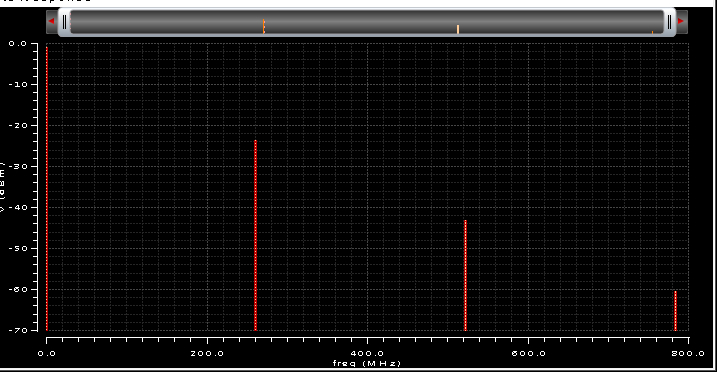
第二个竖线为所需要的振荡频率功率,振荡频率为280M,其他三根竖线是设置的三个谐波边带,为什么最左边的一个频率等于0的谐波边带的功率反而还大于第二个的功率呢?还是我本身就对这个图形理解错误呢?求高人解释,不胜感激!
没进行隔直操作吧,0频处应该包含有直流电源提供的功率吧,我不清楚vco的结构
直流分量功率。
好的,谢谢你的建议。但是为什么振荡频率为280M,也就是第二个边带的功率到-20db这么小了,这个是我要的信号的功率啊,应该至少大于0才对啊,是不是我哪个地方没有设置好啊?
the circuit is ok and this is a usual result ..
simply your results in db means that ur voltage level is less than 1 ..
the DC component is determined by biasing .. ur DC component value is almost 0 db which means that ur oscillation happens around almost 1 V ..
now ur 1st harmonic ~ -21 db which means that ur oscillation is almost 89mv peak .. (20log(.089)=-21db) .. if u plot the magnitude instead of db u will find the values plotted in mv..
actually when designing VCOs u need gain just to make sure ur circuit is gonna oscillate .. ur gm*rp >2 is the condition .. so if u use inductors and caps with higher q factor u can get a better output , or if u increase ur diff pair width u can get higher gm .. u can also increase ur current ..
anyway the csystem u design ur VCO for is what determines the specs needed for output swing level ..
我又学到知识了!太感谢你了!谢谢你这么细心回答!thank you!
“the DC component is determined by biasing .. ur DC component value is almost 0 db which means that ur oscillation happens around almost 1 V ..” 5楼说的这个什么意思呢?
你好我想问一下怎么样能够确定这个振荡器是否起振呢?或者怎样加输入让他起振呢?