如何确定CT sigma-delta 调制器中电流舵DAC的电流大小
yes
非常感谢你的回复。我尚有疑问,控制这15个DAC的信号是量化器的输出,或者为高或者为低,那么DAC的电流方向要么是向外流出,要么是向内流入,也就是如果考虑DAC的电流流向,这15个DAC的电流加起来并不等于240uA,这该如何解释?谢谢。
What do you mean ? Just the total Idac*Rint = fbc*Vref, voila!

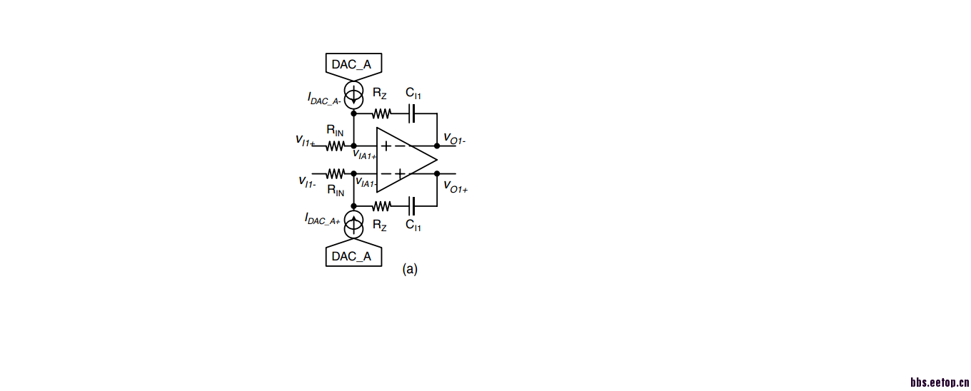
Your connection is right, but simulation method is not right.
If you do DC simulation, the current will flow into input resistos and that leads to voltage difference.
You should do trans simulation. Actually the current is flowing into the integrator, not the input resistors.
Then you will find out that when there is current flowing into integrator, there is voltage difference at the input of the integrator, but it's small. It means when you design your OTA, you should make sure that Gm of the OTA is much larger than 1/Rint to make the input of your OTA as virtual ground, then the voltage difference at the input will be small.

非常感谢你的回答。我是同时做了DC和Tran仿真,然后分析DC时发现了这个问题,DC的偏离值大约有40mV(DC理想值是900mV);我采用的不是Gm-C积分器,而是active RC积分器电路,那么要消除这种DAC电流流过积分电阻而产生的电压偏离,应该满足什么要求呢?
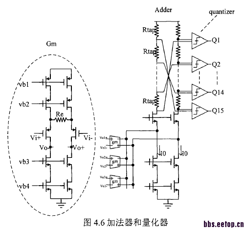
在初步搭建整体回路后,仿真时我先使得差分输入均为900mV的直流,即输入共模点,且差分输入两端电压差为0;那么此时四位量化器的输出应该是1000,也就是中间值。但是发现在前200ns满足,之后就一直不满足了。我无法确定原因。如图分别是加法器和量化器的连接,以及仿真结果。能帮我分析下吗?
非常感谢。
上图中第二栏为理想DAC的输出,白线处应该为正确的结果,200ns之后就不能保持1000了。
could u change the format of ur plot, it's 3.5M, too large, I cannot see it

I know you use active-RC.
Actually, the current does not flow into the resistor, it flows into the integrator.
You can't avoid the voltage difference at the input of your OTA. It always exist.
One way to reduce it is to make Gm of you OTA larger. Another is to reduce the output swing of your integrator.
Delta-sigma modulator need time to work properly, which means the output signal in the first seveal hundred nanoseconds is not correct.
According to your describe, you have no input signal. But delta-sigma actually generate kind of random signal to represent your input signal. Why should you always see 1000 ?
fdgfdgfgfdgfdgfdgfdgfdg
哈哈哈哈