有关如何鉴别QVCO输出的正交特性
提到使用无源混频器,就是下面这种电路。
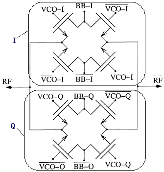
大致的测量思想是,QVCO产生的正交输出送入混品器八个晶体管的栅极VCO(I Q两路),然后通过矢量信号发生器产生一个低频的例如50MHz的可以认为是完美的正交信号,送入BB(I Q两路)。然后在RF(差分输出)得到的输出经50欧姆标准阻抗接入频谱仪。
如果QVCO输出的信号是完美正交的,那么上述电路在不考虑失配等非理想因素下,是可以完全抑制或者说抵消其和频分量而只保留差频的。
而如果有误差,那么根据误差的不同,和频和差频的能量比(不知道是该叫做镜像抑制比呢?还是边带抑制比?)会有所不同。
那么测量镜像抑制比,就可以推算出QVCO高频输出的相位误差是多少,即将相位差转换为能量比进行测量。
推出来的镜像抑制比与相位误差的关系式,跟Razavi射频微电子的第208页是一样的。
不过奇怪的是,仿真出来的镜像抑制比总是比理论值高。试问有谁知道为什么呢?
我用的Spectre 7.1 TSMC 65nm MMRF,使用PSS分析看谐波Power获得镜像抑制比。
SSB Mixer cannot give a reasonable value unless your input IR is 0.
But Many papers use this techniques.
Such as
Han-Jian Lee, Che-Sheng Chen, etc. A mismatch Compensation Circuit for CMOS Quadrature VCO Phase Error.
Pietro Andreani, etc. Analysis and Design of a 1.8-GHz CMOS LC Quadrature VCO, JSSC.
QVCO output is just single tone with phase shift of 0,90,180,270 degree.
And I intend to use some Baseband Quadrature Signal to mix it,
the circuit was designed so as to eliminate the f1+f2 part, if QVCO is perfectly quadrature.
You mentioned the input IR, do you mean the deviation of Baseband Test Signal?
As QVCO output is already considered as imperfect.
Of course yes. LO's must have certain level of I/Q mismatch and that's why you are discussing with me.
I just guess you incited the TB with non-ideal BB signal.
我也有依樣問題