请教:关于Buck DC-DC
是不是由于Io(输出电流)远小于IL(电感电流),因此无论时钟的占空比是多少,电荷在电容上的积累都将使Vout上升?
反过来,假设设计得不好,active状态下Io比较大,会不会按照一定的占空比(如50%)开关功率管,不能使Vout上升?
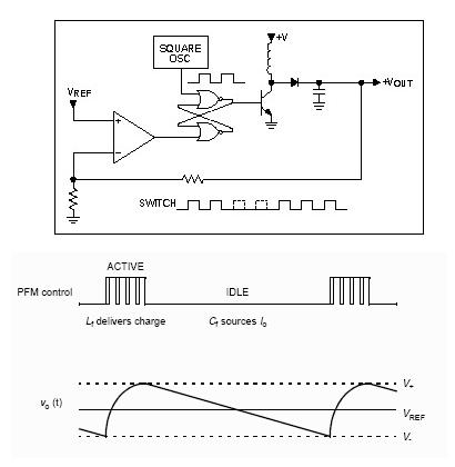
When it is in active mode, the circuit is openloop with a fixed duty cycle clock.
If DVdd > Vo, then whatever Io, inductor current will raise over Io and Vo could reach over target value eventually.
IL=Io/(1-D), D is duty clock, idea 50% duty clock, IL=2Io.
The is the max Io.
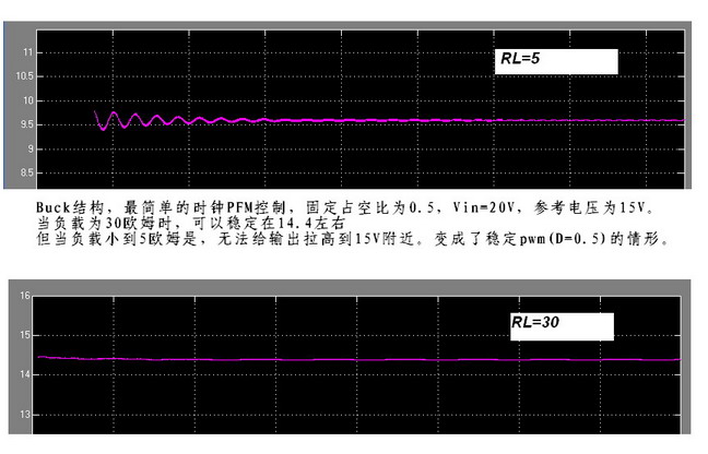
应该还是和Io有关吧...simulink的结果:
轻载,拉高到14.4的情况可以看到IL>Io
而重载,IL=Io
waiting on line...
Vdd = 20V,Vref=15V, D=0.5.
When clk =0, diode is open or close?
If diode is close, the effective D > 0.5, otherwise D < 0.5.
建议小编把Vo ripple and inductor current 的时域图贴上来。
我第一次的回复不太严谨。
我的想法是:
At steay state, taking a look with a long peirod, the effective duty cycle of converter should be D_eff = Vo/Vdd (when operate at CCM).
Thus the input clock duty cycle gives us the upper range of D_eff, or (D_eff)max = D_clk.
At light load, the coverter operates in DCM and D_eff is smaller than Vo/Vdd.
When load arises, D_eff is accordingly larger, the D_eff will be euqal to Vo/Vdd when the converter operates at CCM.
Once converter enters CCM, D_eff should not change in ideal case.
Practically D_eff needs to be larger than Vo/Vdd to compensate the parasitical loss.
Thus, the duty cycle of clock should be larger than Vref/Vdd when we use this topology.
As to your case, when load is light, the converter operates at DCM , therefore, you can get the Vo = 14.4.
While at heavy load, when converter operates at CCM, you can not get a Vo larger than Vdd*D_clk.
果然是DCM模式,当Rl比较大的时候,电感电流下降快,下一个开关周期还没来到,电流就放光了...
感谢peacefeng的耐心解答...
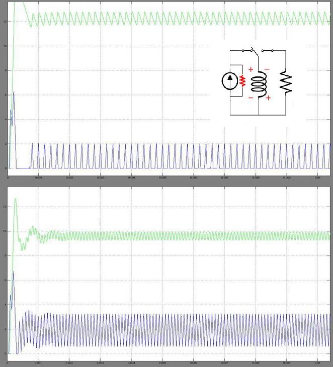
上面的那个结果是把Co改小了一些,所以Vo的过冲大了一些
increasing value of ESR, the overshoot should be smaller....
没有看懂。虽然是做功率管的。