CMW500测试CC3200的wifi性能,如发射功率、灵敏度问题
硬件环境:
(1)CC3200
(2)罗德CMW500是 测试wifi性能的仪器
软件环境:
CC3200 作为station,CMW500作为AP,CC3200 连接CMW500。 CMW500作为服务端,CC3200作为客户端。
现在想用CMW500测试CC3200的wifi性能,如发射功率、灵敏度之类的。请问CC3200的测试程序怎样编写,有什么建议?是否可以利用tcp_socket 编程例程?目前不能知道CMW500 的端口号
CC3100 & CC3200 Radio Tool
(Redirected from CC31xx & CC32xx Radio Tool)
![]()
![]()
Contents
- 1 Introduction
- 2 Features
- 3 Releases
- 4 Preparation
- 4.1 Software downloads
- 4.2 Hardware
- 5 Radio Tool Installation Directory
- 6 Hardware connections
- 6.1 3100 Booster pack + Emulation board
- 6.2 3200 LaunchPad
- 7 Flashing the board
- 7.1 CC3100
- 7.2 CC3200
- 8 GUI Version
- 8.1 TX Testing
- 8.2 RX Testing
- 8.3 Insertion Loss calibration
- 9 CLI Version
- 9.1 Usage
- 9.2 Example Commands
- 10 Hardware connections on Non TI EVMs
- 11 Error Codes
- 12 Known Issues
- 13 Appendix A: APIs for Accessing Library Functions
- 13.1 Radio Tool API
- 13.1.1 RadioToolOpen (CC3100 SPI)
- 13.1.2 RadioToolOpen (UART)
- 13.1.3 RadioToolClose
- 13.1.4 RadioStartTX
- 13.1.5 RadioStopTX
- 13.1.6 RadioStartRX
- 13.1.7 RadioStopRX
- 13.1.8 RadioGetStats
- 13.1.9 RadioGetMacAddr
- 13.1.10 RadioGetDeviceVersion
- 13.2 Type definition
- 13.2.1 Primitive types
- 13.2.2 Struct types
- 13.1 Radio Tool API
- 14 Appendix B: Source Code For Developers
- 14.1 CC3200 Application Source
- 15 Links
Introduction
The main usage of the Radio Tool is to serve as a control panel for direct access to the Radio. It can be used for the RF evaluation and for certification purposes (Like FCC, ETSI, Telec etc.). The tool is expected to work seamlessly on TI evaluation platforms: Boosterpack+ FTDI emulation board for 3100 and Launchpad for 3200. If customers want to use the tool on their final platform please refer to the section 10 "Hardware connections on Non TI EVMs". The IO levels of these lines should be kept at VBAT level (same voltage that powers the 3100/3200 device).
Please refer to CC31xx Datasheet and CC32xx Datasheet for reference RF numbers.
Features
- Connection Type
- CC3100 via SPI
- CC3100 via UART
- CC3200 via UART
- Acquires MAC address
- Acquires FW information
- TX
- Continuous
- Packetized
- CW
- RX
- Statistics
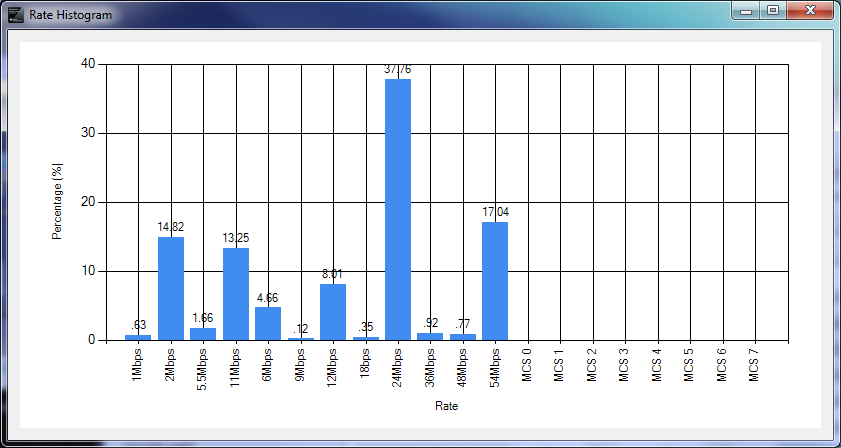
- RSSI Histogram
- Rate Histogram
Releases
The changelog can be found in the released binary package.
| Radio Tool Version | Download | Release Date | Matching ServicePack Version | Compatible devices | Special Notes |
|---|---|---|---|---|---|
| 1.2 (Latest) | Latest Download | Mar 10th, 2016 | 1.0.1.6-2.6.0.5 | See the complete list at CC31xx Release Notes and CC32xx Release Notes | |
| 1.1_fix | 1.1_fix Download | Aug 6th, 2015 | 1.0.0.10.0 | See the complete list at CC31xx Release Notes 1.1.0and CC32xx Release Notes 1.1.0 | This version resolved the CW issue seen in 1.1. However, some manual fixes are still required. Please see the highlighted section below. |
| 1.1 | 1.1 Download | Mar 13th, 2015 | 1.0.0.10.0 | See the complete list at CC31xx Release Notes 1.1.0and CC32xx Release Notes 1.1.0 | |
| 1.0 | 1.0 Download | Sept 12th, 201 | 1.0.0.1.2, 1.0.0.1.1 | See the complete list at CC31xx Release Notes 1.0.0and CC32xx Release Notes 1.0.0 | |
| 0.5 | 0.5 Download | June 12th, 2014 | 0.5.2.0.1 | See the complete list at CC31xx Release Notes 0.5.2and CC32xx Release Notes 0.5.2 |
![]() Note: The Radio Tool version matches SDK verion. For example, if the Radio Tool has a version as 0.5.x.x, you'll need to flash the devices with Service Pack 0.5.x.
Note: The Radio Tool version matches SDK verion. For example, if the Radio Tool has a version as 0.5.x.x, you'll need to flash the devices with Service Pack 0.5.x.
|
Warning: We found a flaw in SDK 1.1.0 causing the Carrier Wave(CW) to malfunction. In general, you'll experience the following problem when using RadioTool 1.1: |
This is partially fixed in the version 1.1_fix. For CC3100, the fix is already incorporated in the source code and binary. For CC3200, only the provided binary file has this fix applied because this requires the user to modify the simplelink\source\driver.c source file as provided in the SDK. If you are using the provided cc3200 binary, no action is required from your end. If you need to compile your own radio tool binary file with the corrected CW mode functionality, please incorporate the following change: In line 805 of simplelink\source\driver.c, please change from:
if (pCmdExt && pCmdExt->RxPayloadLen < 0 && pCmdExt->TxPayloadLen) to:
if (pCmdExt && pCmdExt->RxPayloadLen < 0) Please note that this change is only for fixing the CW issue for radio tool (or transceiver mode). If your application does not utilize this functionality, please change it back to default as we do not know the side effect of this change outside of radio tool context. |
Preparation
Software downloads
- See #Releases
![]() Note: These are required in order to run the Radio Tool application. A DLL error during running with regards to MSVCR100.dll will occur if any of these are missing.
Note: These are required in order to run the Radio Tool application. A DLL error during running with regards to MSVCR100.dll will occur if any of these are missing.
- Microsoft .NET Framework 4
- Microsoft Visual C++ 2010 Redistributable Package (x86) (install even if using x64 machine)
- Microsoft Visual C++ 2010 Redistributable Package (x64) (if using a x64 machine)
- Microsoft Visual C++ 2010 SP1 Redistributable Package (x86) (install even if using x64 machine)
- Microsoft Visual C++ 2010 SP1 Redistributable Package (x64) (if using a x64 machine)
Hardware
See the latest complete list of supported hardware at CC31xx Release Notes and CC32xx Release Notes.
Radio Tool Installation Directory
The installation process is pretty straight by following the steps. The default installation location is C:\TI, but you are able to change it to anywhere you want.
Here's the file directory structure after installation:
- Installation directory
-
- RadioToolApplication
- The Radio Tool GUI application (RadioToolGUI.exe), Radio Tool CLI application (RadioToolCLI.exe), and 3 pre-compiled DLL files (CC3100Lib.dll, CC3100LibUART.dll, CC3200Lib.dll). - RadioToolApplication_Source
- The Radio Tool application source for development. Use Visual Studio to open the file RadioToolApp.sln. - CC32xxBoardApplication_Binary
- CC32xx MCU images. Use these with Uniflash in order to flash a MCU image onto the device. See Flashing the board section. - CC32xxBoardApplication_Source
- CC32xx MCU image source for development. Place the radiotool folder under your CC3200 SDK example directory, and use CCS to open the project in the ccsfolder inside.
Hardware connections
3100 Booster pack + Emulation board
Connect the RF connector (J2 or J3) to a WLAN tester/RF equipment for measurements and the J1 USB connector on the emulation board to the PC. Make sure the RF connection to the instrument in made BEFORE powering ON the board so that the right load impedance is provided during power ON.
The RF path to J3 (murata RF switch) is always present. In case you want to use J2 (uFL)for RF measurements the path to the antenna needs to be disconnected (depopulate R6) and path to J2 connector is enabled by populating R7.
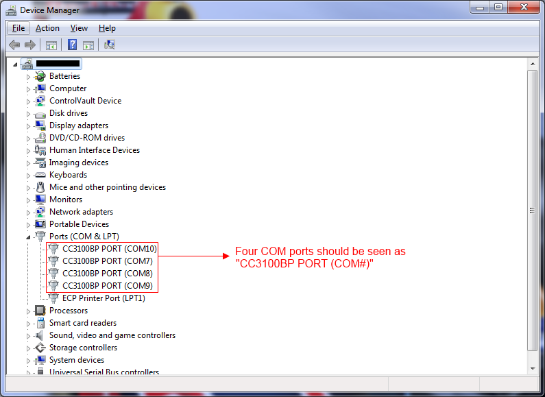
- Using UART interface
The emulation board would enumerate the following UART ports on the PC , select the 3rd COM port in the tool.
- Using SPI interface
SPI interface doesn't require users to choose a specific COM port. Simply select the "CC3100 SPI" option in the tool to start connection.
![]() Warning: With SPI connection, only one CC3100 can be connected to a PC at the same time because the Radio Tool doesn't know which CC3100 device to connect to if multiple CC3100 devices are present.
Warning: With SPI connection, only one CC3100 can be connected to a PC at the same time because the Radio Tool doesn't know which CC3100 device to connect to if multiple CC3100 devices are present.
For large number testings, we recommend using the "CC3100 UART".
3200 LaunchPad
Connect the RF connector (J18 or J24) to a WLAN tester/RF equipment for measurements and the USB connector on the LaunchPad to the PC.Make sure the RF connection to the instrument in made BEFORE powering ON the board so that the right load impedance is provided during power ON.
The RF path to J24 (murata RF switch) is the default. Incase you want to use J18 (uFL) for RF measurements you need to disconnect the J24 path (depopulate R111) and enable the J18 path by populating R110.
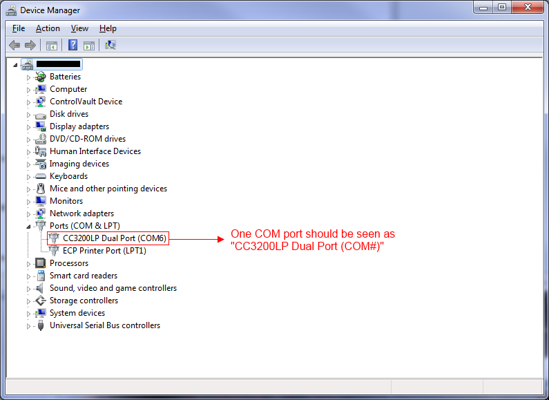
The LaunchPad would enumerate the following COM port on the PC. Select that COM port in the GUI.
Flashing the board
The devices need to be flashed with the correct firmware in order to operate this tool correctly. Please refer to the #Releases section for the correct servicepack and/or application binary to be flashed.
CC3100
Please refer to the CC31xx & CC32xx UniFlash for instruction on how to flash firmware onto the CC3100 board.
CC3200
Put on the SOP2 jumper.
Please refer to the CC31xx & CC32xx UniFlash for instruction on how to flash the board with firmware and application binary. The binary files can be found in the CC32xxBoardApplication Binary folder.
After finishing flashing, be sure to remove the SOP2 jumper in order to run the ob-board application.
GUI Version
The GUI tool provides a user friendly interface to use the radio tool.
You have three types of devices for connection:
- CC3100 SPI
- Note: This is not recommended to use because you can only connect to one CC3100 board with this protocol, if more than one CC3100 is present. CC3100 UART is the recommended connection.
- CC3100 UART
- CC3200 UART
With UART connection type selected, you can pick from a list of known COM port and baudrates. Click on the blue spinning arrows on the right to refresh the list if you don't see the COM port showing up. If you still don't see your port showing up, please check your device connection and make sure you have the latest FTDI profile flashed. See CC31xx & CC32xx FTDI Flashing for details.
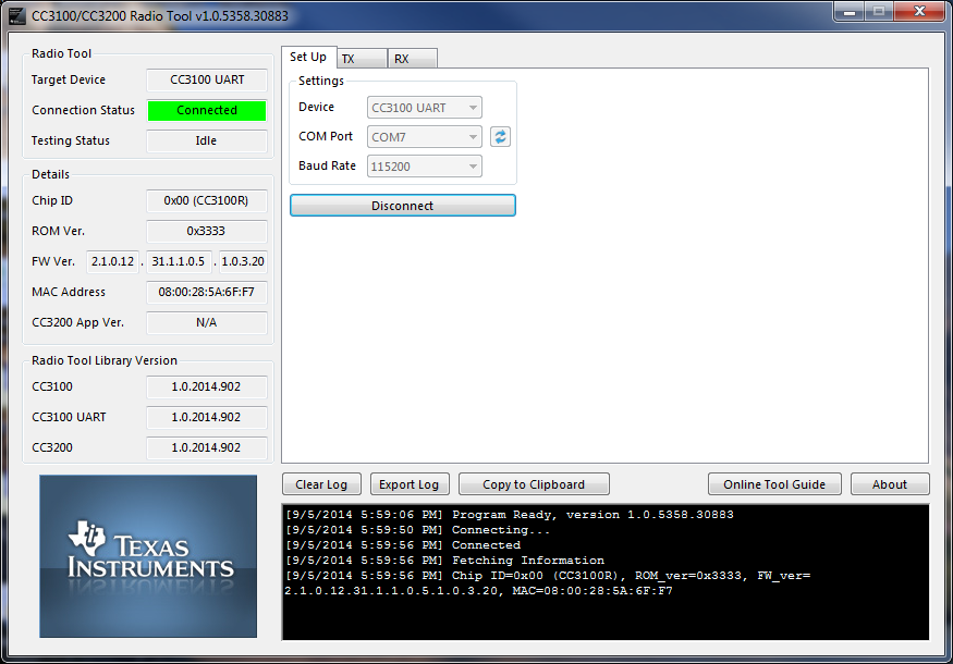
Upon a successful connection, the Details box on the left will tell you detailed device information on the connected device. This is a good chance to make sure you board is flashed with a desired image version.
FW Ver. (or Firmware version), is arranged in the following way: <NWP version>.<FW version>.<PHY version>
The CC3200 App Ver. information is only for CC3200, indicating the application version flashed onto the device.
The only baud rate supported right now is 115200.
TX Testing
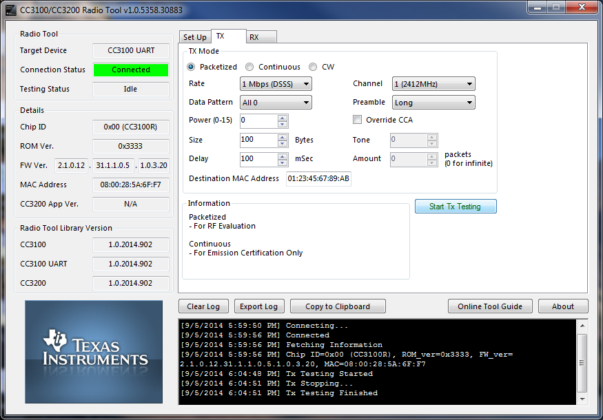
There are three types of TX testings supported:
| Packetized | Each packet is sent one at a time from the application MCU to the network processor. There is a large delay between packets in this mode. Generally used for RF evaluation. |
|---|---|
| Continuous | This is a test mode where the network processor sends out packets back to back in an internal loop, without the intervention of host MCU. The delay between packets is typically very small and hence useful for FCC/ETSI certification purposes where high duty cycle is required. Only used for emission Certification. |
| CW (Carrier Wave) | In this mode the device transmits an un-modulated RF tone. The frequencies can be selected in steps of 312.5Khz. Note that the power output with tone 0 is very low. Incase higher RF power is desired use tone numbers other than 0. |
Some fields will be disabled/enabled, depending on the testing type you want to run. For example, Amount will only be disabled when Continuous testing type is selected.
Parameter explanation:
| Parameter | Range (inclusive) | Description |
|---|---|---|
| Rate | 802.11 PHY Data Rate | |
| Channel | [1, 13] | 802.11 2.4GHz band WiFi channel. 14 is not supported |
| Data Pattern | ||
| Preamble | [Long, Short] | OFDM preamble is automatically configured bt the device when OFDM rates are selected. |
| Power level | [0-15] | 0 being the maximum power and 15 being the minimum power. |
| Override CCA | [Yes, No] | Enable this field for CCA (Clear Channel Assessment) override if the WiFi environment is too congested to have a reliable periodic transmission. |
| Size | [24, 1400] | Packet size, in Bytes |
| Tone | [-25, 25] | CW only. 0 means tone at center frequency. A value N between within the range [-25, 25] means tone at offset N*312.5kHz. |
| Delay | [100, 1000000] | Delay of transmission, in milliseconds (mSec). |
| Amount | [0, 4294967290] | Number of packets to transmit. A value of 0 indicates infinite number of packets. |
| Destination MAC address | The destination MAC address in packets. |
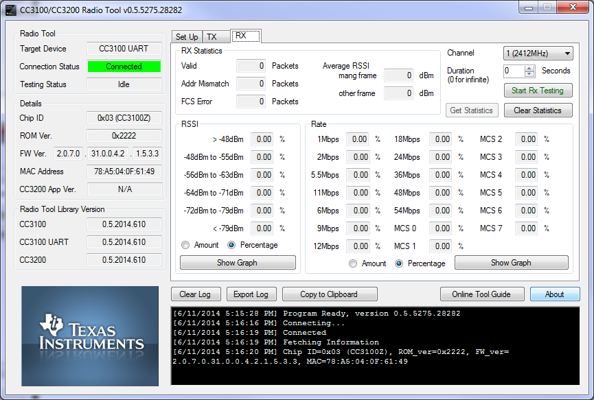
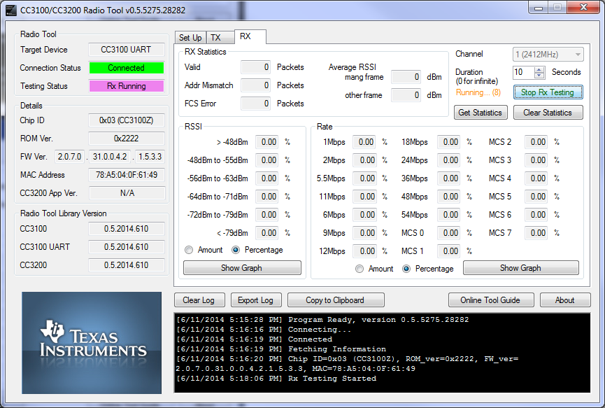
RX Testing
The RX Testing is used for gathering WiFi statistics in the air within a specified channel.
- Duration
Statistics gathering time can be specified with a fixed duration, or 0 to make the testing time indefinite, until user presses the STOP button to stop. Statistics will be gathered automatically whenever a RX testing is stopped. However, users may choose to gather the statistics any time before RX testing ends by clicking the button Get Statistics.
Fields explanation:
| Addr Mismatch | Packets with address mismatch |
|---|---|
| FCS Error | Frame Check Sequence error |
| mang frame | Average RSSI in management frames |
| other frame | Average RSSI in other frames |
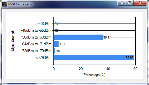
The following screenshot shows gathered statistics. Rates and RSSIs are displayed as percentages.
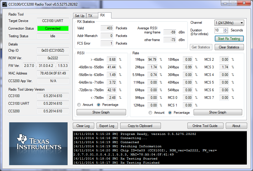
Users may also click on the Show Graph buttons to show a bar graph representation of rates or RSSI.
|
|
|---|
Insertion Loss calibration
The TX power levels and Rx sensitivity numbers quoted in the datasheet are at the device RF pin. Additional loses due to onboard filter, PCB trace, connectors and cables used to connect to the external equipment should be accounted for seperatly by adding their insertion losses.
On the TI EVMs the onboard filter insertion loss is typically 1dB (max of 1.35dB), the PCB trace + RF connector loss is ~0.4 dB. These need to be accounted for while evaluating the performance. Incase the user has a different filter or a different trace on their PCB the user needs to measure their insertion loss seperatly. The insertion loss of the cable used to connect the EVM to the external equipment can be measured using a network analyzer.
CLI Version
The CLI tool provides a traditional command line version of the radio tool. This is particularly useful when performing large scale automated testings. The RadioToolCLI.exe application is located at the RadioToolApplication directory. Use CMD or batch files to execute commands.
Usage
Usage: RadioToolCLI -X [-P=port] [-B=baud] [-M] [-F] [-T|-R]
       RadioToolCLI [-h|--help] [-i|--info]

Options:
Miscellaneous:
  -h, --help                 Shows this message
  -i, --info                 Shows RadioToolCLI and radio tool library version and information.
  -v                         increase debug message verbosity

Device Connection:
  -X, --target=TARGET        The TARGET testing device. 0:CC3100 SPI, 1:CC3100 UART, 2:CC3200 UART. REQUIRED.
                               Range: [0, 2]. Default: 1
  -P, --port=VALUE           The port number of the target testing platform.
                               Required for UART connections. Range: [0, 255].
  -B, --baud_rate=BAUD RATE  The BAUD RATE of the target COM port.
                               Required for UART connections. Range: [0, Int32.MaxValue].
  -M, --mac                  Returns the MAC address
  -F, --firmware             Returns the firmware version and CC3200 application version (if applicable) in the following order:
                               Chip ID, ROM version, Firmware version, CC3200 App version, MAC address.

Common for TX and RX:
  -t, --duration=DURATION    RX/TX Testing DURATION in seconds for -T and -R options. Range: [1, 65535]. Default: 1
  -c, --channel=CHANNEL      RX/TX Testing CHANNEL  for -T and -R options. Range: [1, 13]. Default: 1

TX (Transmission):
  -T, --tx                   TX testing for Continuous or Packetized.
  -z, --tx_type=TX_TYPE      TX Testing TX_TYPE. 1:Continuous, 2:Packetized, 3:CW. 'tone_offset' option can be used if
                               and only if CW is chosen. Range: [1, 3]. Default: 1.
  -m, --rate, --modulation=MODULATION
                             TX Testing rate (with the corresponding MODULATION). Range: [1, 20]. Default: 1 (1Mbps DSSS).
                               1: 1 Mbps (DSSS)
                               2: 2 Mbps (DSSS)
                               3: 5.5 Mbps (CCK)
                               4: 11 Mbps (CCK)
                               5: NOT SUPPORTED
                               6: 6 Mbps (OFDM)
                               7: 9 Mbps (OFDM)
                               8: 12 Mbps (OFDM)
                               9: 18 Mbps (OFDM)
                               10: 24 Mbps (OFDM)
                               11: 36 Mbps (OFDM)
                               12: 48 Mbps (OFDM)
                               13: 54 Mbps (OFDM)
                               14: MCS 0
                               15: MCS 1
                               16: MCS 2
                               17: MCS 3
                               18: MCS 4
                               19: MCS 5
                               20: MCS 6
                               21: MCS 7
  -w, --power=POWER          TX POWER attenuation for Continuous and Packetized testing. 0 being the maximum power and
                               15 being the minimum power.Range: [0, 15]. Default: 0
  -f, --tone_offset=TONE_OFFSET
                             TX TONE_OFFSET for CW testing only. A value of N means tone at offset N*312.5kHz.
                               Range: [-25, 25]. Default: 0
  -l, --packet_size=SIZE     TX Testing packet SIZE. Range: [24, 1400]. Default: 1400
  -o, --cca_override         TX CCA override enable. Default: non-overriding.
  -a, --dest_mac=MAC         TX destination MAC address WITHOUT colons. For example, if the MAC address is 01:23:45:67:89:AB,
                               enter 0123456789AB instead. Case insensitive. Default: 01:23:45:67:89:AB
  -n, --amount=VALUE         TX maximum number of packets. Continuous TX only. Range:[0, 4,294,967,290]. 0 for
                               infinite amount. Default: 0
  -g, --delay=VALUE          TX delay in between packets in milliseconds. Packetized TX only. Range:[100, 1,000,000].
                               Default: 100
  -e, --preamble=VALUE       TX preamble. Long:0, Short:1. Default: Long
  -r, --pattern=VALUE        TX data pattern. See the following for the complete list. Default: 0 (All 0)
                               0: All 0
                               1: All 1
                               2: Incremental
                               3: Decremental

RX (Reception):
  -R, --rx                   RX testing and retrieves statistics. The statistics will be shown as:
                               1st line: <# valid packets>, <# FCS error packets>, <# address mismatch packets>
                               2nd line: <Average RSSI in management frame>, <Average RSSI in other frames>
                               3rd line: RSSI historgram. <greater than -48dBm>, <-48dBm to -55dBm>, <-56dBm to -63dBm>, <-64dBm to -71dBm>, <-72dBm to -79dBm>, <less than -79dBm>
                               4th line: Rate historgram, lowest to highest. The list order is identical to the rate/
                               modulation option.
  -d, --report_period=N      RX statistics reporting period, every N seconds. If set to 0, RX statistics will only report at the end.
                               Range: [0, 65535]. Default: 0
  -p, --report_percent       Report RX histogram in percentage format. If not set, default is in amount of packets.
Example Commands
::Show the help page
RadioToolCLI.exe -h
 ::Show the help page
RadioToolCLI.exe --help
 ::Show the help page
RadioToolCLI.exe /h
::Show the Firmware version and MAC address of CC3100 via UART
RadioToolCLI.exe -X1 -P7 -B115200 -F
::TX Continuous
::CC3100 via SPI
::channel 1
::1Mbps DSSS
::max power
::packet size 1400bytes
::destination MAC address 01:23:45:67:89:AB
::infinite amount of packets
::long preamble
::all 0 pattern
::1 second testing time
RadioToolCLI.exe -X0 -T
::TX Continuous
::CC3100 via UART
::channel 1
::54Mbps OFDM
::max power
::packet size 1400bytes
::destination MAC address 01:23:45:67:89:AB
::infinite amount of packets
::long preamble
::all 0 pattern
::10 seconds testing time
RadioToolCLI.exe -X1 -P7 -B115200 -T -z1 -c1 -m13 -w0 -l1400 -a 0123456789AB -n0 -e0 -r0 -t10
::TX Packetized
::CC3200 via UART
::channel 1
::1Mbps DSSS
::max power
::packet size 512bytes
::destination MAC address EE:EE:EE:EE:0E:EE
::100ms delay
::long preamble
::incremental pattern
RadioToolCLI.exe -X2 -P7 -B115200 -T -z2 -c1 -m1 -w0 -l512 -a EEEEEEEE0EEE -n0 -e0 -r1 -t10
::TX CW
::CC3100 via SPI
::channel 6
::1Mbps DSSS
::-10 OFFSET (-3.125Mhz)
RadioToolCLI.exe -X0 -T -z3 -c6 -m1 -f -10 -t10
::RX
::CC3100 via UART
::channel 6
::show as number of packets
::20 seconds testing time
::only report statistics at the end
RadioToolCLI.exe -X1 -P7 -B115200 -c6 -R -t20
 ::sample output
1289, 459, 0
-72, -83
0, 0, 69, 9, 562, 170, 479
156, 156, 329, 344, 264, 14, 1, 8, 7, 155, 7, 0, 4, 0, 0, 0, 0, 0, 0, 0, 0
RX Finished: SUCCESS
::RX
::CC3100 via UART
::channel 11
::show as percentage
::5 seconds testing time
::report statistics every 1 second
::verbose
RadioToolCLI.exe --target=1 --port 7 /baud_rate 115200 -c11 /R -d=1 /t=5 -v
 ::sample output
Connecting...
Connected
RX Testing Started
RX Testing Started. The program will last 5 second(s) and report every 1 second(s)
345, 72, 0
-60, -67
9, 9, 191, 4, 65, 0, 76
0, 0, 116, 2, 51, 14, 0, 34, 38, 48, 0, 0, 42, 0, 0, 0, 0, 0, 0, 0, 0
1094, 47, 0
-62, -78
157, 157, 397, 13, 31, 0, 496
0, 0, 78, 0, 31, 22, 0, 5, 6, 470, 1, 2, 479, 0, 0, 0, 0, 0, 0, 0, 0
1254, 92, 0
-60, -77
216, 216, 430, 14, 32, 0, 562
1, 1, 114, 1, 39, 19, 1, 2, 2, 530, 10, 9, 526, 0, 0, 0, 0, 0, 0, 0, 0
409, 66, 0
-62, -76
18, 18, 173, 29, 32, 1, 156
0, 0, 114, 0, 34, 14, 2, 7, 6, 112, 9, 10, 101, 0, 0, 0, 0, 0, 0, 0, 0
837, 74, 0
-61, -79
70, 70, 347, 36, 21, 0, 363
0, 0, 84, 0, 54, 19, 1, 2, 1, 333, 6, 10, 327, 0, 0, 0, 0, 0, 0, 0, 0
RX Finished: SUCCESS
Hardware connections on Non TI EVMs
In order to use the RadioTool on a platform other than TI EVMs the interface signals from the Emulation board can be wired to the corresponding pins on the custom platform. Note that the signal voltage level from the Emulation board LaunchPad is 3.3V and the VCC level is 3.3V. This VCC can also be used to power the 3X00 device on the custom platform. Make sure the IO voltage levels between the emulation board and the device on the EVM and same.
- Connections for emulation board to 3100 platform. Use the 3100 UART option in the tool.
| Line | CC3100 Pin | Emulation board pin |
|---|---|---|
| Vcc | P1.1 | |
| UART1_TX | 55 | P1.3 |
| UART1_RX | 57 | P1.4 |
| UART1_CTS | 61 | P4.4 |
| UART1_RTS | 50 | P4.5 |
| GND | P2.1 | |
| nHIB | 2 | P1.5 |
- Connections from LaunchPad to 3200 platform.
| Line | CC3200 Pin | LaunchPad pin |
|---|---|---|
| Vcc | J12 pin2 (remove J12 jumper) | |
| UART1_TX | 55 | J7 pin 3 (Remove J7 jumper) |
| UART1_RX | 57 | J6 pin 3 (Remove J6 jumper) |
| GND | P2.1 |
Error Codes
Occasionally you may experience error due to application error or user error. Here we are providing a list of error codes and their description.
| CC3100 Error Codes | CC3200 Error Codes |
|---|---|
|
|
Known Issues
- Select a wrong port will hang the entire program. This is cause by not having a time-out for connection.
- Device disconnection will not provide any warning to the user.
- If the CC3x00Lib.dll does not load, install the windows redistributable packages, see http://e2e.ti.com/support/wireless_connectivity/f/968/t/358800
Appendix A: APIs for Accessing Library Functions
From this point and on contains information about utilizing the radio tool source and library. You may stop here if you just want to use the radio tool as it is.
The followings are the API functions used in the Radio Tool library files. You may access the three library files (CC3100Lib.dll, CC3100LibUART.dll, and CC3200Lib.dll) directly without the use of Radio Tool GUI application for your own tool development.
|
Extended content | ||||||||||||||||||||||||||||||||||||||||||||||||||||||||||||||||
|---|---|---|---|---|---|---|---|---|---|---|---|---|---|---|---|---|---|---|---|---|---|---|---|---|---|---|---|---|---|---|---|---|---|---|---|---|---|---|---|---|---|---|---|---|---|---|---|---|---|---|---|---|---|---|---|---|---|---|---|---|---|---|---|---|
|
Radio Tool APIThe API calls are pretty much identical for CC3100 and CC3200, with the exception of SPI connection, which doesn't require a COM port or baud rate like UART does. RadioToolOpen (CC3100 SPI)
INT32 RadioToolOpen()
RadioToolOpen (UART)
INT32 RadioToolOpen(UINT8 comPort, UINT32 baudRate)
RadioToolClose
INT32 RadioToolClose()
RadioStartTX
INT32 RadioStartTX(RadioTxMode_e      eTxMode,
                   INT8               powerLevel_Tone,
                   Channel_e          eChannel,
                   RateIndex_e        eRate,
                   RadioPreamble_e    ePreamble,
                   RadioDataPattern_e eDataPattern,
                   UINT16             size,
                   UINT32             delay_amount,
                   UINT8              overrideCCA,
                   UINT8              *pDstMac)
RadioStopTX
INT32 RadioStopTX(RadioTxMode_e eTxMode)
RadioStartRX
INT32 RadioStartRX(Channel_e eChannel)
RadioStopRX
INT32 RadioStopRX()
RadioGetStats
INT32 RadioGetStats(UINT32 *validPackets,
                    UINT32 *fcsPackets,
                    UINT32 *addrMMPackets,
                    INT16  *avgRssiMgmt,
                    INT16  *avgRssiOther,
                    UINT16 *pRssiHistogram,
                    UINT16 *pRateHistogram)
RadioGetMacAddr
INT32 RadioGetMacAddr(UINT8 *pMacAddress)
RadioGetDeviceVersion
INT32 RadioGetDeviceVersion(UINT8 *pDevVersion)
Type definitionThe following definitions are used in the PC-based library functions. Primitive types
Struct types
typedef enum
{
    RADIO_TX_CONTINUOUS = 1,
    RADIO_TX_PACKETIZED = 2,
    RADIO_TX_CW         = 3,
    MAX_RADIO_TX_MODE   = 0xff
}RadioTxMode_e;
The Max power level is 0. The lowest power level is 15
typedef enum
{
    HIGH_GAIN_STEP_0      = 0,
    HIGH_GAIN_STEP_1      = 1,
    HIGH_GAIN_STEP_2      = 2,
    HIGH_GAIN_STEP_3      = 3,
    MID_GAIN_STEP_0       = 4,
    MID_GAIN_STEP_1       = 5,
    MID_GAIN_STEP_2       = 6,
    MID_GAIN_STEP_3       = 7,
    MID_GAIN_STEP_4       = 8,
    MID_GAIN_STEP_5       = 9,
    MID_GAIN_STEP_6       = 10,
    MID_GAIN_STEP_7       = 11,
    MID_GAIN_STEP_8       = 12,
    MID_GAIN_STEP_9       = 13,
    MID_GAIN_STEP_10      = 14,
    MID_GAIN_STEP_11      = 15,
    MAX_RADIO_POWER_LEVEL = 0xff
}RadioPowerLevel_e;
typedef enum
{
    CHANNEL_1    = 1,
    CHANNEL_2    = 2,
    CHANNEL_3    = 3,
    CHANNEL_4    = 4,
    CHANNEL_5    = 5,
    CHANNEL_6    = 6,
    CHANNEL_7    = 7,
    CHANNEL_8    = 8,
    CHANNEL_9    = 9,
    CHANNEL_10   = 10,
    CHANNEL_11   = 11,
    CHANNEL_12   = 12,
    CHANNEL_11   = 13,
    MAX_CHANNELS = 0xff
}RadioChannel_e;
typedef enum
{
    RATE_1M       = 1,
    RATE_2M       = 2,
    RATE_5_5M     = 3,
    RATE_11M      = 4,
    RATE_6M       = 6,
    RATE_9M       = 7,
    RATE_12M      = 8,
    RATE_18M      = 9,
    RATE_24M      = 10,
    RATE_36M      = 11,
    RATE_48M      = 12,
    RATE_54M      = 13,
    RATE_MCS_0    = 14,
    RATE_MCS_1    = 15,
    RATE_MCS_2    = 16,
    RATE_MCS_3    = 17,
    RATE_MCS_4    = 18,
    RATE_MCS_5    = 19,
    RATE_MCS_6    = 20,
    RATE_MCS_7    = 21,
    MAX_NUM_RATES = 0xFF
}RadioRateIndex_e;
typedef enum
{
    LONG_PREAMBLE_MODE         = 0,
    SHORT_PREAMBLE_MODE        = 1,
    OFDM_PREAMBLE_MODE         = 2,
    N_MIXED_MODE_PREAMBLE_MODE = 3,
    GREENFIELD_PREAMBLE_MODE   = 4,
    MAX_NUM_PREAMBLE           = 0xff
}RadioPreamble_e;
typedef enum
{
    ALL_0_PATTERN       = 0,
    ALL_1_PATTERN       = 1,
    INCREMENTAL_PATTERN = 2,
    DECREMENTAL_PATTERN = 3,
    PN9_PATTERN         = 4,
    PN15_PATTERN        = 5,
    PN23_PATTERN        = 6,
    MAX_NUM_PATTERN     = 0xff
}RadioDataPattern_e;
typedef struct
{
    UNIT16 DeviceRadioToolAppVersion[2]
    UINT32 ChipId;
    UINT32 FwVersion[4];
    UINT8  PhyVersion[4];
    UINT32 NwpVersion[4];
    UINT16 RomVersion;
    UINT16 Padding;
}DeviceVersion_s;
Note: Chip IDs and corresponding names:
|
Appendix B: Source Code For Developers
Source codes of the radio tool can be found in the installtion location. You'll need:
- Visaul Studio (2010 SP1 minimum)
- Full-featured IAR Workbench for ARM (please check with your SDK version for a proper IAR version to use)
CC3200 Application Source
The CC3200 on-board application source can be found in the CC32xxBoardApplication_Source directory. Simply copy this into the example folder of your SDK. Use CCS to open the project workspace.