如何使用CC2640的硬件定时器进行捕获
需要跟一般mcu(51 430)一样配置相关定时器Timer寄存器,指定哪个IO作为输入pin,计数方向等等?
用来捕获某个pin的电平变化(1K-2KHz)的脉冲波,通过计算1秒钟的脉冲数(如果是每次脉冲都触发中断,那在中断里自加计捕获中断次数)
user guide 里面没有相关定时器Timer的API描述, 只有PWM。TI的手册文档太多太乱了,找个硬件寄存器文档都麻烦。有关于TimerA与TimerB的相关描述(在technical reference manual文档13节Timer,模式操作包括寄存器描述),好像是1个32Bit分成2个16bit的使用,但是没有例程,是直接写寄存器还是RTOS里带有相关配置API,包括pin的配置复用成capture input,脉冲上升/下降沿触发捕获中断,等等主要信息。
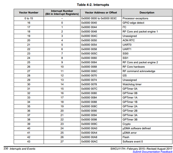
触发中断后中断子程序怎么写,没有找到相关历程,定时器的中断向量?
关于定时器捕获脉冲这方面几乎没有一点信息。。。。有大神做过捕获的demo吗?虚心请赐教!
您可以参考CC26XXWARE driverlib 的文档
CC26XXWARE是包含在ti-rtos内的 C:\ti\tirtos_cc13xx_cc26xx_2_20_01_08\products\cc26xxware_2_24_02_17393\driverlib
Susan Yang
您可以参考CC26XXWARE driverlib 的文档
CC26XXWARE是包含在ti-rtos内的 C:\ti\tirtos_cc13xx_cc26xx_2_20_01_08\products\cc26xxware_2_24_02_17393\driverlib
Hi,Susan
我找到在你给我的路径下找到Timer.c与Timer.h,里面有些我想要的关键点。但是还有一些疑问
具体如下:
Timer.h文件中
extern void TimerConfigure(uint32_t ui32Base, uint32_t ui32Config);定时器的配置函数
以下是此函数说明,我只截取了部分
//! When configuring for a pair of half-width timers, each timer is separately
//! configured. The timers are configured by setting \c ui32Config to
//! the bitwise OR of one of each of the following three:
//! instead of down.
//! - \ref TIMER_CFG_A_CAP_COUNT : Half-width edge count capture
//! - \ref TIMER_CFG_A_CAP_COUNT_UP : Half-width edge count capture that counts
//! up instead of down.
//! - \ref TIMER_CFG_A_CAP_TIME : Half-width edge time capture
//! - \ref TIMER_CFG_A_CAP_TIME_UP : Half-width edge time capture that counts up
//! \param ui32Base is the base address of the timer module.
//! \param ui32Config is the configuration for the timer.
也就是可以通过此函数将TimerA或TimerB配置成Capture模式, 第一个函数参数我的理解是通用定时器GPT0,GP1,GPT2,GPT3的基址 (CC2640共4个32bit硬件Timer),目前还没找到第一个参数在哪里定义,第二个函数参数在上面可以找到:
#define TIMER_CFG_A_CAP_COUNT 0x00000003 // Timer A event counter
#define TIMER_CFG_A_CAP_COUNT_UP 0x00000013 // Timer A event up-counter
#define TIMER_CFG_A_CAP_TIME 0x00000007 // Timer A event timer
#define TIMER_CFG_A_CAP_TIME_UP 0x00000017 // Timer A event up-count timer
在指定使用哪个硬件定时器作为capture后,配置上升/下降沿捕获,这个函数很好理解
__STATIC_INLINE void
TimerEventControl(uint32_t ui32Base, uint32_t ui32Timer, uint32_t ui32Event)
一个参数跟上面一样,第二个是选择TimerA/TimerB(1个32bit timer分2个16bit timer用),第三个参数就是选择触发沿
#define TIMER_A 0x000000FF // Timer A
#define TIMER_B 0x0000FF00 // Timer B
#define TIMER_BOTH 0x0000FFFF // Timer Both
#define TIMER_EVENT_POS_EDGE 0x00000000 // Count positive edges
#define TIMER_EVENT_NEG_EDGE 0x00000404 // Count negative edges
#define TIMER_EVENT_BOTH_EDGES 0x00000C0C // Count both edges
extern void TimerIntRegister(uint32_t ui32Base, uint32_t ui32Timer,
void (*pfnHandler)(void));注册对应定时器中断服务程序回调*pfnHandler
TimerIntEnable(uint32_t ui32Base, uint32_t ui32IntFlags) 使能定时器具体事件中断
TimerIntClear(uint32_t ui32Base, uint32_t ui32IntFlags) 清楚中断标志
#define TIMER_CAPA_EVENT 0x00000004 // CaptureA event interrupt
#define TIMER_CAPA_MATCH 0x00000002 // CaptureA match interrupt
TimerEnable(uint32_t ui32Base, uint32_t ui32Timer) 打开定时器
以上是我能理解的部分,还有的疑问就是在哪里设置某个IO(IOID1 2 3...?)为信号输入引脚
还有定时器的时钟来源?TimerPrescaleSet(uint32_t ui32Base, uint32_t ui32Timer, uint32_t ui32Value)是分频设置0-255
分频的时钟源是从哪里来的?
在TIRTOS中我是否可以直接在我的task中使用Timer.c Timer.h?
定时器计数值多少我可以不用管,只要每次捕获到从pin输入的信号的上升or下降沿就触发中断,通过1秒内记录中断次数来记录脉冲频率
谢谢!