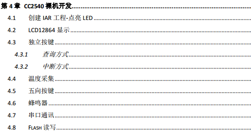
CC2650裸机
求CC2650裸机程序。谢谢!就像如下目录似的。

xiaobailong,
一切尽在TI的wiki上:http://processors.wiki.ti.com/index.php/Category:BluetoothLE
SDK,示例代码。
仔细找总能找到你需要的。
主要是还没有一个写2541的又通篇不提TI的书出现
您好,xiaobailong24 :
请问您找到裸机的2650的示例了么,我也一直在找,在论坛上也发帖多次了,cc26xxware这个软件包也没有示例代码,用这个软件包写uart一直没有成功,已经更改很多次了,也是不好使,但是GPIO是好使的,附上连接 http://www.ti.com.cn/tool/cn/cc26xxware?keyMatch=CC26xxWare&tisearch=Search-CN-Everything
您好 HG:
我认为的一般使用串口的使用过程:
1、打开GPIO时钟
2、打开uart时钟
3、设置IO为RXD TXD
4、uart配置 包括波特率 系统时钟 停止位 数据位 校验位等等
5、使能串口
6、使用查询方式发送或者接收数据
void main()
{
PRCMPeripheralRunEnable(PRCM_PERIPH_UART0);//开启串口时钟
PRCMLoadSet();//开启串口时钟
PRCMPeripheralRunEnable(PRCM_PERIPH_GPIO);//开启GPIO时钟
PRCMLoadSet();//开启GPIO时钟
IOCPinTypeUart(UART0_BASE, IOID_2 , IOID_3 , IOID_UNUSED, IOID_UNUSED);//开启GPIO时钟
//设置 uart0 波特率115200 数据长度8 1个停止位
UARTConfigSetExpClk(UART0_BASE, SysCtrlClockGet(),115200,UART_CONFIG_WLEN_8 | UART_CONFIG_STOP_ONE | UART_CONFIG_PAR_NONE);
UARTFIFOLevelSet(UART0_BASE, UART_FIFO_TX7_8, UART_FIFO_RX7_8);//配置FIFO中断
UARTEnable(UART0_BASE);//使能uart0
// UARTDisable(UART0_BASE);//失能uart0
while(1)
{
// 接收一个字符
// TempChar = (uint8_t)UARTCharGet(UART0_BASE);
// 发送一个字符
UARTCharPut(UART0_BASE, 0x55);
}
你好,还没找到呢。你能操作GPIO吗?可以的话发一个例程给我吧,我也是刚刚接触才开始学习,谢谢啦。大家一起进步!邮箱:1531095190@stu.tjpu.edu.cn
好的,我找找看,谢谢!
您好 xiaobailong24,
IO 是这么设置的,还缺少一个开启GPIO的时钟,我还没找到在哪里设置呢。
IOCPinTypeGpioOutput(IOID_6);
IOCPinTypeGpioOutput(IOID_7);
GPIOPinWrite(GPIO_PIN_6 | GPIO_PIN_7,0);
好的,谢谢。但是你能把完整的工程发给我一份吗?有些工程设置我有点不明白,例如头文件包含路径啥的。邮箱告诉你了。
您好xiaobailong24,
我也是新手,他这个文件路径我也设置不明白,我是直接用他的例程来改的。
您好,xiaobailong24,
给你一段完整的GPIO输出初始化和使用的程序,我尝试过的
void main(void)
{
PRCMPowerDomainOn(PRCM_DOMAIN_PERIPH);
while((PRCMPowerDomainStatus(PRCM_DOMAIN_PERIPH)
!= PRCM_DOMAIN_POWER_ON));
/* Enable GPIO peripheral */
PRCMPeripheralRunEnable(PRCM_PERIPH_GPIO);
PRCMLoadSet();
while(!PRCMLoadGet());
IOCPinTypeGpioOutput(IOID_6);
IOCPinTypeGpioOutput(IOID_7);
IOCPinTypeGpioOutput(IOID_25);
IOCPinTypeGpioOutput(IOID_27);
GPIOPinWrite(GPIO_PIN_6 | GPIO_PIN_7 | GPIO_PIN_25 | GPIO_PIN_27,1);
while(1);
}
xiaobailong24,
附上串口程序:
/* Which events to trigger a UART interrupt */
#define CC26XX_UART_RX_INTERRUPT_TRIGGERS (UART_INT_RX | UART_INT_RT)
/* All interrupt masks */
#define CC26XX_UART_INTERRUPT_ALL (UART_INT_OE | UART_INT_BE | UART_INT_PE | \
UART_INT_FE | UART_INT_RT | UART_INT_TX | \
UART_INT_RX | UART_INT_CTS)
/*---------------------------------------------------------------------------*/
#define cc26xx_uart_isr UART0IntHandler
/*---------------------------------------------------------------------------*/
static int (*input_handler)(unsigned char c);
/*---------------------------------------------------------------------------*/
void InitGpio(void)
{
PRCMPowerDomainOn(PRCM_DOMAIN_PERIPH);
while((PRCMPowerDomainStatus(PRCM_DOMAIN_PERIPH)
!= PRCM_DOMAIN_POWER_ON));
/* Enable GPIO peripheral */
PRCMPeripheralRunEnable(PRCM_PERIPH_GPIO);
PRCMLoadSet();
while(!PRCMLoadGet());
IOCPinTypeGpioOutput(IOID_6);
IOCPinTypeGpioOutput(IOID_7);
IOCPinTypeGpioOutput(IOID_25);
IOCPinTypeGpioOutput(IOID_27);
GPIOPinWrite(GPIO_PIN_6 | GPIO_PIN_7 | GPIO_PIN_25 | GPIO_PIN_27,0);
}
void UartConfig(void)
{
//power_and_clock(void)
/* Power on the SERIAL PD */
PRCMPowerDomainOn(PRCM_DOMAIN_SERIAL);
while(PRCMPowerDomainStatus(PRCM_DOMAIN_SERIAL)
!= PRCM_DOMAIN_POWER_ON);
/* Enable UART clock in active mode */
PRCMPeripheralRunEnable(PRCM_PERIPH_UART0);
PRCMLoadSet();
while(!PRCMLoadGet());
// //accessible(void)
// /* First, check the PD */
// if(PRCMPowerDomainStatus(PRCM_DOMAIN_SERIAL)
// != PRCM_DOMAIN_POWER_ON) {
// return false;
// }
// /* Then check the 'run mode' clock gate */
// if(!(HWREG(PRCM_BASE + PRCM_O_UARTCLKGR) & PRCM_UARTCLKGR_CLK_EN)) {
// return false;
// }
// //disable_interrupts(void)
// /* Acknowledge UART interrupts */
// IntDisable(INT_UART0);
// /* Disable all UART module interrupts */
// UARTIntDisable(UART0_BASE, CC26XX_UART_INTERRUPT_ALL);
// /* Clear all UART interrupts */
// UARTIntClear(UART0_BASE, CC26XX_UART_INTERRUPT_ALL);
//
// //enable_interrupts(void)
// /* Clear all UART interrupts */
// UARTIntClear(UART0_BASE, CC26XX_UART_INTERRUPT_ALL);
// /* Enable RX-related interrupts only if we have an input handler */
// if(input_handler) {
// /* Configure which interrupts to generate: FIFO level or after RX timeout */
// UARTIntEnable(UART0_BASE, CC26XX_UART_RX_INTERRUPT_TRIGGERS);
// /* Acknowledge UART interrupts */
// IntEnable(INT_UART0);
// }
//configure(void)
uint32_t ctl_val = UART_CTL_UARTEN | UART_CTL_TXE;
/*
* Make sure the TX pin is output / high before assigning it to UART control
* to avoid falling edge glitches
*/
IOCPinTypeGpioOutput(IOID_3);
GPIOPinWrite(GPIO_PIN_3, 1);
/*
* Map UART signals to the correct GPIO pins and configure them as
* hardware controlled.
*/
IOCPinTypeUart(UART0_BASE, IOID_2, IOID_3,
IOID_UNUSED, IOID_UNUSED);
/* Configure the UART for 115,200, 8-N-1 operation. */
UARTConfigSetExpClk(UART0_BASE, SysCtrlClockGet(),
115200,
(UART_CONFIG_WLEN_8 | UART_CONFIG_STOP_ONE |
UART_CONFIG_PAR_NONE));
/*
* Generate an RX interrupt at FIFO 1/2 full.
* We don't really care about the TX interrupt
*/
UARTFIFOLevelSet(UART0_BASE, UART_FIFO_TX7_8, UART_FIFO_RX4_8);
/* Enable FIFOs */
HWREG(UART0_BASE + UART_O_LCRH) |= UART_LCRH_FEN;
// if(input_handler) {
// ctl_val += UART_CTL_RXE;
// }
ctl_val += UART_CTL_RXE;
/* Enable TX, RX (conditionally), and the UART. */
HWREG(UART0_BASE + UART_O_CTL) = ctl_val;
}
*/
IOCPinTypeGpioOutput(IOID_3);
GPIOPinWrite(GPIO_PIN_3, 1);
/*
* Map UART signals to the correct GPIO pins and configure them as
* hardware controlled.
*/
IOCPinTypeUart(UART0_BASE, IOID_2, IOID_3,
IOID_UNUSED, IOID_UNUSED);
/* Configure the UART for 115,200, 8-N-1 operation. */
UARTConfigSetExpClk(UART0_BASE, SysCtrlClockGet(),
115200,
(UART_CONFIG_WLEN_8 | UART_CONFIG_STOP_ONE |
UART_CONFIG_PAR_NONE));
UARTFIFOLevelSet(UART0_BASE, UART_FIFO_TX7_8, UART_FIFO_RX4_8);
/* Enable FIFOs */
HWREG(UART0_BASE + UART_O_LCRH) |= UART_LCRH_FEN;
ctl_val += UART_CTL_RXE;
/* Enable TX, RX (conditionally), and the UART. */
HWREG(UART0_BASE + UART_O_CTL) = ctl_val;
}
void main(void)
{
uint8_t Led = 1;
uint8_t TempChar;
uint32_t delay;
uint32_t i;
//外部时钟初始化
oscillators_select_lf_xosc();
//GPIO初始化
InitGpio();
for(delay=0;delay<50000;delay++)
{
for(i=0; i<100; i++);
}
GPIOPinWrite(GPIO_PIN_6 | GPIO_PIN_7 | GPIO_PIN_25 | GPIO_PIN_27,1);
UartConfig();
GPIOPinWrite(GPIO_PIN_6 | GPIO_PIN_7 | GPIO_PIN_25 | GPIO_PIN_27,0);
while(1)
{
UARTCharPut(UART0_BASE, TempChar++);
// for(delay=0;delay<50000;delay++)
// {
// for(i=0; i<100; i++);
// }
if(Led != 0)
Led = 0;
else
Led = 1;
GPIOPinWrite(GPIO_PIN_6 | GPIO_PIN_7 | GPIO_PIN_25 | GPIO_PIN_27,Led);
TempChar = (uint8_t)UARTCharGet(UART0_BASE);
if(TempChar == '1')
break;
}
}
好的,但是头文件和工程设置需要修改哪些地方?方便截图给我吗,谢谢!
另外你用的是什么套件,我用的是CC2650STK + DEVPACK。
关注!还没有机会用过这个芯片啊。
把GPIO的工程发给我一份吧。邮箱:1531095190@stu.tjpu.edu.cn
xiaobailong24,
是TI官方的一个软件包,我也忘了在哪里下载的了,名称ble_cc26xx_setupwin32_2_01_00_44423
里面有示例 目录为C:\ti\simplelink\ble_cc26xx_2_01_00_44423\Projects\ble下面有部分示例,直接把我发给你的代码,就可以在示例工程里使用。
UART调试成功了吗?我找到了UART的例程,请参考附件3.1 Creating Example Projects Using the TI Resource Explorer
GPIO控制CC2650STK的LED1、LED2和BUZZER,根据官方例程修改。
已经调试通了,我上面贴的代码就可以用了,使用查询方式 来进行串口的接收与发送。
你好 jingpeng xi
//外部时钟初始化
oscillators_select_lf_xosc();
这个在哪里
