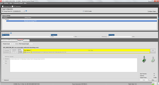
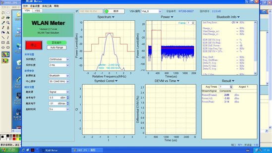
CC2640测试射频指标时数据无解调
CC2640测试射频指标时数据无解调,是否要发相应的固定代码。但SmartRF Studio 7的工具没有找到相应的设置选项。请问如何解此问题?


可以用hostest 例子,配合BTOOL来做
http://processors.wiki.ti.com/index.php/PTM_cc2640
PTM cc2640
Bluetooth Low Energy Main Page
Contents
[hide]- 1 Introduction
- 1.1 Direct Test Mode (DTM)
- 1.2 Production Test Mode (PTM)
- 1.3 PTM vs. DTM
- 2 How to add Production Test Mode to a CC2640 Application
- 2.1 The following application project modifications are necessary:
- 2.2 The following stack project modifications are necessary.
- 3 Using PTM
- 3.1 Test Commands
Introduction
This page will describe Production Test Mode (PTM) which allows a BLE application in a "single-chip" configuration to temporarily expose the host control interface (HCI) test commands over the UART interface when triggered externally to do so (e.g. holding a GPIO pin low during power up). This test mode allows the device to be connected to a Bluetooth RF Tester in order to run Direct Test Mode (DTM) commands on a production line using the final release firmware, while leaving the UART GPIO pins available for the application to use at all other times. Note that this page only considers UART, and not SPI, as the transport protocol since it uses the least amount of GPIO's and throughput is not a factor for DTM.
Direct Test Mode (DTM)
DTM is a standard method for testing BLE devices using the DTM HCI commands. A number of wireless test equipment manufactures, including Anritsu (MT8852B) and Rhode and Schwarz, make BLE Testers that use this mode. It is very useful to use these testers during development or on the production line in order to verify the RF performance of a BLE system. Complementary to these testers, it is also possible to create your own PC application that sends these DTM commands over the serial link. DTM is very well described in the Bluetooth Core Specification Volume 6 Part F. All DTM commands as well as TI Vendor Specific modem test commands are accessible in embedded (single-device) application via API calls as well as over HCI in the Host_Test sample application. Refer to the TI Vendor Specific HCI guide in the documents folder of your BLE-Stack SDK. Application Note Configuring the CC2640 for Bluetooth Direct Test Mode (SWRA530)describes the hardware and software configuration for running DTM on the CC2640 / CC2640R2F with standard Bluetooth test equipment.
Production Test Mode (PTM)
One problem with DTM is that it relies on a certain stack configuration (network processor with HCI exposed over UART) in order to work with the testers, though many end-applications don’t use this configuration. This would require the customer, during production, to flash the wireless MCU with a network processor image (e.g., host_test) before testing, and then re-flash with the final product image. To circumvent this, the TI BLE-Stack has implemented a feature called Production Test Mode (PTM), which allows for an embedded software application to support direct test mode without exposing the HCI to the UART pins under normal operation.
Note that the pins used for PTM can also be used for an application UART interface. In this case, it is necessary to ensure that the other device that is connected to the UART interface does not run at the same time that DTM is being exercised. If the device powers up and goes into PTM mode (by a GPIO being held high or low or some other stimulus), the UART will then be used for DTM commands. If the device powers up normally and does not go into PTM mode, then the UART can be initialized by the application and used to communicate with the other device.
DTM commands can also be called by the embedded BLE application.
PTM vs. DTM
Sometimes the question is asked, "What is the difference between PTM and DTM?". As described above, the test commands themselves are defined as DTM and accessed via HCI network processor (e.g., Host_Test). PTM is simply a means to access DTM commands in non-network processor configuration. Entering PTM (e.g., via a pogo pin driving a GPIO) exposes these same DTM commands over a UART interface to a single-device (non-network processor) firmware configuration.
How to add Production Test Mode to a CC2640 Application
This section will describe the steps to add PTM to the simpleBLEPeripheral application on the SmartRF06 board. The UART interface will be over the RS-232 of the mini-USB cable attached to the SmartRF06. A PC terminal application will be used to send DTM commands and communicate with the SmartRF06. Note that the network processor interface (NPI) that is used in the network processor project (HostTestApp) will be used to expose the HCI interface via UART for PTM. This requires adding an additional task to the project which in turn will require modifications of both the application and stack project.
The following application project modifications are necessary:
1. Add the following NPI files from $INSTALL$/Components/npi and $INSTALL$/Components/npi/inc
- npi_tl_uart.c
- npi_tl_uart.h
- npi_config.h
- npi_tl.c
- npi_tl.h
- npi_frame.h
- npi_frame_hci.c
- npi_rxbuf.c
- npi_rxbuf.h
- npi_task.c
- npi_task.h
2. If it is desired to only use a 2-wire UART (that is, to not use the CTS and RTS handshaking), make the following code replacements in all of the above files:
Note: This procedure is required if using the UART back-channel on the TI development kits (SmartRF06 / CC2650 LaunchPad).
- Replace
#ifdef POWER_SAVING
with
#if 0
- Replace
#infdef POWER_SAVING
with
#if 1
3. Add the search path to the NPI files to the "Additional include directories" in the Preprocessor Options:
- $PROJ_DIR$/../../../../../../../Components/npi
- $PROJ_DIR$/../../../../../../../Components/npi/inc
4. Add the following define to the application project's preprocessor defined symbols:
- NPI_USE_UART
5. In order to account for the additional NPI task, increment the following preprocessor defines as shown:
- ICALL_MAX_NUM_TASKS=4
- ICALL_MAX_NUM_ENTITIES=7
6. In main.c, construct the NPI task:
#include "inc/npi_task.h"
main()
{
...
   NPITask_createTask(ICALL_SERVICE_CLASS_BLE);
...
7. Set the task priorities so that NPI has higher priority than the GAPRole and application task.
- in npi_task.c, set NPITASK_PRIORITY to 3
- in peripheral.c, set GAPROLE_TASK_PRIORITY to 2
- in simpleBLEPeripheral.c, set SBP_TASK_PRIORITY to 1
8. Select the pins to be used for TX and RX. These are set by default in Board.h as:
#define Board_UART_RX        IOID_2
#define Board_UART_TX        IOID_3
These pins are correct for using the RS-232 cable in this demo.
9. Add PTM enable code to the application initialization function. In this example, the SmartRF06's right button is used to decide whether or not to enter PTM. That is, PTM is entered only if the button is pressed upon reset. This is implemented in SimpleBLEPeripheral_init() as :
#include <ti/drivers/pin/PINCC26XX.h>
#include <ti/drivers/Power.h>
#include <ti/drivers/power/PowerCC26XX.h>
static void SimpleBLEPeripheral_init(void)
{
  ICall_registerApp(&selfEntity, &sem);

  if (!(PIN_getInputValue(Board_KEY_RIGHT))) //enter PTM
  {
    //prevent PM
    Power_setConstraint(Power_SB_DISALLOW);
    Power_setConstraint(Power_IDLE_PD_DISALLOW);

    //enable PTM
    HCI_EXT_EnablePTMCmd();
  }

  else  //proceed as normal
  {
...
Note that all of the original SimpleBLEPeripheral_init() functionality besides the ICall registration now resides in the else() statement when PTM is not entered. That is, if PTM is not to be entered, the application should proceed as normal.
The following stack project modifications are necessary.
1. Because we added another task (NPI) which needs to communicate with the stack, the default OSAL_MAX_NUM_PROXY_TASKS value needs to be increased. Add the following preprocessor defined symbol:
- OSAL_MAX_NUM_PROXY_TASKS=3
2. Set the compiler option to include PTM library functions in buildConfig.opt:
/* Include Transport Layer (Full or PTM) */
/* -DHCI_TL_NONE */
-DHCI_TL_PTM
/* -DHCI_TL_FULL *
3. If they are not already part of the stack project, add the following files which can be found at $INSTALL$\Projects\ble\common\npi\npi_np\CC26xx\Stack:
- npi.c
- npi.h
4. If step 3 was necessary, then also add the search path to find these files in the "Additional Include Directories" in the C/C++ Compiler Tab of the Project Options:
- $PROJ_DIR$/../../../../../../../Components/npi
Note! If a linking error occurs, it is likely due to the Flash Boundary tool and a recompilation should fix it. See the Software Developer's Guide included with the installer for more information.
Using PTM
With this code added to the project and he SmartRF06's right button held down during reset, the device will enter PTM upon reset. A terminal application, such as HCITester, can then communicate with the device under test (DUT) via UART through a Windows COM port using the following settings:
- Baud Rate = 115200
- Flow Control = None
- Parity = None
- Stop Bits = 1
- Data Bits = 8
Note: Make sure the terminal application is configured to send raw binary without any additional control characters (e.g., CR/LF).
Test Commands
This section will list the DTM commands and corresponding events that can be used for testing.
HCI_LE_Transmitter_Test
Send this hex command to start Tx test:
01 1E 20 03 xx yy zz
xx = the channel you want to transmit on, any value from 0x00 to 0x27 (BLE channels go from 0 to 39)
yy = length of payload bytes in each test packet, which can be any value from 0x00 to 0x25
zz = code for the type of data in the packet payload. The following values can be used
- 0x00 Pseudo-Random bit sequence 9
- 0x01 Pattern of alternating bits ‘11110000’
- 0x02 Pattern of alternating bits ‘10101010’
- 0x03 Pseudo-Random bit sequence 15
- 0x04 Pattern of All ‘1’ bits
- 0x05 Pattern of All ‘0’ bits
- 0x06 Pattern of alternating bits ‘00001111’
- 0x07 Pattern of alternating bits ‘0101’
After sending the HCI_LE_Transmitter_Test command to the DUT, the following response will be returned, indicating that the command was received and the Tx test has begun:
04 0E 04 01 1E 20 00
HCI_LE_Receiver_Test
Send this hex command to start Rx test:
01 1D 20 01 xx
xx = the channel you want to receive on, which can be any value from 0x00 to 0x27 (BLE channels go from 0 to 39)
After sending the HCI_LE_Receiver_Test command to the device, the following response will be returned, indicating that the command was received and the Rx test has begun:
04 0E 04 01 1D 20 00
HCI_LE_Test_End
Send this hex command to end Rx or Tx test:
01 1f 20 00
After sending the HCI_LE_Test_End command to the device, the following response will be returned, indicating that the command was received and the test has ended:
04 0e 06 01 1f 20 00 xx xx
xx xx = 00 00 if Tx test was performed
xx xx = Total number of received packets if Rx test was performed.
Other Commands
The following HCI Extension commands can also be used for DTM to facilitate regulatory testing (e.g., ETSI, FCC, etc.). These are described in the HCI Vendor Specific API Guide included with the BLE-Stack installer (documents folder):
- HCI Extension Modem Test Transmit
- HCI Extension Modem Hop Test Transmit
- HCI Extension Modem Test Receive
- HCI Extension End Modem Test
- HCI Extension Set BDADDR
- HCI Extension Set Tx Power
- HCI Extension Set Max DTM Tx Power
- HCI Extension Build Revision
- HCI Extension Reset System
|
For technical support please post your questions at http://e2e.ti.com. Please post only comments about the article PTM cc2640 here. |
|
Links | |||
|
Category:
- CC2640
Navigation menu
- Log in
- Request account
- Page
- Discussion
- Read
- View source
- View history
- Main Page
- All pages
- All categories
- Recent changes
- Random page
- Help
Print/export
- Create a book
- Download as PDF
- Printable version
Toolbox
- What links here
- Related changes
- Special pages
- Permanent link
- Page information


