CC2640F128RSMR 44 封装,出现 能下载,不能debug 的问题?
在2640 7*7 做的大板用于工程 样机 调测功能没问题,并调通 了 gyro 等 传感器等主要功能,,,,但是,小批量公司 要做成 小板用在产品上,出现 能下载 不能 debug 的问题,,硬软件 工程师 搞了 一周 找不到 问题?
量取 电压等 正常,
请 大神 帮忙!
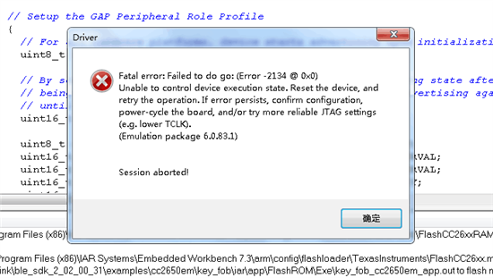
这是Flash Programmer 2的下载状态提示,是OK的......但在IAR里安调试按钮就不能下载和调试!
>Initiate access to target: XDS-TIZ89C3EA.
>Reading file: C:/ti/simplelink/ble_sdk_2_02_00_31/examples/cc2650em/key_fob/iar/stack/FlashROM/Exe/key_fob_cc2650em_stack.hex.
>Reading file: C:/ti/simplelink/ble_sdk_2_02_00_31/examples/cc2650em/key_fob/iar/app/FlashROM/Exe/key_fob_cc2650em_app.hex.
>Start flash erase ...
>Erase finished successfully.
>Start flash programming ...
>Programming finished successfully.
>Start flash verify ...
>Skip verification of unassigned page: 8.
>Skip verification of unassigned page: 9.
>Skip verification of unassigned page: 10.
>Skip verification of unassigned page: 11.
>Skip verification of unassigned page: 12.
>Skip verification of unassigned page: 13.
>Skip verification of unassigned page: 14.
>Skip verification of unassigned page: 15.
>Page: 0 verified OK.
>Page: 1 verified OK.
>Page: 2 verified OK.
>Page: 3 verified OK.
>Page: 4 verified OK.
>Page: 5 verified OK.
>Page: 6 verified OK.
>Page: 7 verified OK.
>Page: 16 verified OK.
>Page: 17 verified OK.
>Page: 18 verified OK.
>Page: 19 verified OK.
>Page: 20 verified OK.
>Page: 21 verified OK.
>Page: 22 verified OK.
>Page: 23 verified OK.
>Page: 24 verified OK.
>Page: 25 verified OK.
>Page: 26 verified OK.
>Page: 27 verified OK.
>Page: 28 verified OK.
>Page: 29 verified OK.
>Page: 30 verified OK.
>Page: 31 verified OK.
>Verification finished successfully.
>Reset target ...
>Reset of target successfull.
芯片版本和生产日期是多少?
你调试工具用的什么?连Flash Programmer2有没有提示升级固件?
Flash program 2版本是1.7.4,没有提示要升级!
刚通电识别不了芯片型号,刷新后才可识别!
调测 工具 是 XDS100
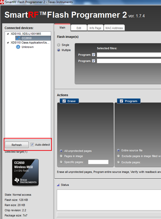
把Auto-detect选上,点击Refresh,然后点击CC2640右键Connect。能识别到就OK了
Michael wong,
你4*4mm芯片在用Flash Programmer下载程序后能正常运行吗?我个人觉得你是没有在对应IAR程序中更改对应的头文件和配置。TI 例程默认是支持7*7mm的,如果改为4*4mm芯片,你需要在对应的地方更改头文件,让其IO和外设对应正确才行。包括射频对应的配置。且还得看你的射频是单端还是差分的。
Michael wong ,
我找了一下我之前简单记录,你可以参考一下。
对应TI官方本身3个不同尺寸的EVM板,配置也不同,如果你要设计自己的RF,可以参考下面内容:
在bleUserConfig.h和.C中
// RF Front End Mode and Bias Configuration
#if defined( CC2650EM_7ID )
#define RF_FE_MODE_AND_BIAS ( RF_FE_DIFFERENTIAL | \
RF_FE_INT_BIAS )
#elif defined( CC2650EM_5XD ) || defined( CC2650EM_4XD )
#define RF_FE_MODE_AND_BIAS ( RF_FE_DIFFERENTIAL | \
RF_FE_EXT_BIAS)
#elif defined( CC2650EM_4XS )
#define RF_FE_MODE_AND_BIAS ( RF_FE_SINGLE_ENDED_RFP | \
RF_FE_EXT_BIAS )
#else // unknown device package
#error "***BLE USER CONFIG BUILD ERROR*** Unknown package type!"
#endif // CC2650EM_7ID
自己配置的方法如下:
/
// Device Package and Evaluation Module (EM) Board
//
// The CC26xx device comes in three types of packages: 7x7, 5x5, 4x4.
// For each package, the user may change how the RF Front End (FE) is
// configured. The possible FE settings are provided as a set of defines.
// (The user can also set the FE bias, the settings of which are also provided
// as defines.) The user can change the value of RF_FE_MODE_AND_BIAS to
// configure the RF FE as desired. However, while setting the FE configuration
// determines how the device is configured at the package, it is the PCB the
// device is mounted on (the EM) that determines how those signals are routed.
// So while the FE is configurable, how signals are used is fixed by the EM.
// As can be see, the value of RF_FE_MODE_AND_BIAS is organized by the EM
// board as defined by EMs produced by Texas Instruments Inc. How the device
// is mounted, routed, and configured for a user product would of course be
// user defined, and the value of RF_FE_MODE_AND_BIAS would have to be set
// accordingly; the user could even dispense with the conditional board
// compiles entirely. So too with the usage of the Tx Power tables. As can be
// seen in bleUserConfig.c, there are two tables, one for packages using a
// differental FE, and one for single-end. This too has been organized by TI
// defined EMs and would have to be set appropriately by the user.
//
// For example:
// Let's say you decided to build several boards using the CC26xx 4x4 package.
// For one board, you plan to use a differential RF FE, while on the other you
// wish to use a single ended RFN RF FE. You would then create your own board.h
// (located by your preprocessor Include path name) that contains one of two
// defines that you create (say MY_CC26xx_4ID and MY_CC26xx_4XS). Then you can
// define your own choice of RF FE conditionally based on these defines
// (completely replacing those shown below), as follows:
//
//#if defined( MY_CC26xx_4ID )
//
// #define RF_FE_MODE_AND_BIAS ( RF_FE_DIFFERENTIAL | \
// RF_FE_INT_BIAS )
//#elif defined( MY_CC26xx_4XS )
//
// #define RF_FE_MODE_AND_BIAS ( RF_FE_SINGLE_ENDED_RFN | \
// RF_FE_EXT_BIAS )
//#else // unknown device package
// :
//
// In this way, you can define your own board I/O settings, and configure your
// RF FE based on your own board defines.
//
你好,
你是不是没有正确加载4X4芯片的头文件。
你需要在IAR设置里面首先修改preprocessor里面的pre define
把CC2650DK_7ID 改为CC2650DK_4XS.
另外你还要加一个4XS的定义文件:
增加下面路径:
#elif defined(CC2650DK_4XS)
#include <../../boards/CC2650DK_4XS/Board.h>
#include <../../boards/CC2650DK_4XS/CC2650DK_4XS.c>
这都是在工程文件里面xxx_board.c文件里面有!
感谢各位的 关注和回复。
已经用各位的建议在查代码和 重新测试了!
有任何进展 给大家报告和回复。
thx
感谢 各位的 回复和关注。
这个问题 搞定了,,最根本的原因 是 那个 10uH 的电感,我们用错,采购成了 10nH 的。现在 已经 优化代码了。
10uH 很难找到 0402 封装的,挺遗憾的。只能先用 0805大 封装的了。
并用 打算,继续使用CC2640 R2 版本 测试。