使用pwm的情况下,低功耗问题。
电机调速程序中pwm初始化代码如下所示:
PIN_Config timerPinTable[] = { PWM_OPEN_IOID | PIN_GPIO_OUTPUT_EN | PIN_GPIO_LOW | PIN_PUSHPULL | PIN_INPUT_DIS | PIN_DRVSTR_MAX,
PIN_TERMINATE };
void board_pwm_init()
{
#ifdef PWM_EXAMPLE
//RTOS: Enable peripheral domain and clocks for timer
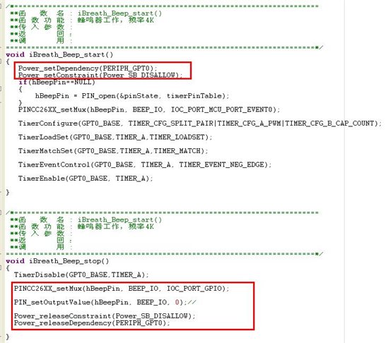
Power_setDependency(PERIPH_GPT0);
//RTOS: Disallow standby while timer is running
//Power_setConstraint (Power_SB_DISALLOW);-----------------------------------
//RTOS: Open and assign pins through PIN driver
hPin = PIN_open(&pinState, timerPinTable);
// RTOS: Route pin to timer0A module
// IOC Port events 0-7 are mapped to GPT timers 0A,0B,1A,1B...3B
PINCC26XX_setMux(hPin, PWM_OPEN_IOID, IOC_PORT_MCU_PORT_EVENT0);
// Timer A in PWM mode, don't care about Timer B but ASSERTS in driverLib requires it
// to be set to something
TimerConfigure(GPT0_BASE, TIMER_CFG_SPLIT_PAIR|TIMER_CFG_A_PWM|TIMER_CFG_B_CAP_COUNT);
}
电机控制结束后调用关闭pwm接口如下:
void board_pwm_stop()
{
TimerDisable(GPT0_BASE,TIMER_A);
Power_setConstraint (Power_STANDBY);
}
调用关闭pwm接口同时配置成输出低电平 但是低功耗进不了了。。。
如果你使用GPTimer/PWM module实现PWM的话,无法进入低功耗,推荐使用sensor controller 实现
PS:可以重点看下gpioGenPulseTrain这个函数
您的意思是我需要安装Sensor Controller Studio工具下编写pwm驱动程序才可以进入低功耗吗?现在我是用IAR编译调试程序的。
您好,打扰了。有没有相关的user guide和demo可供参考。
建议基于TI-RTOS,直接调用TI-RTOS提供的driver,参考如下link,基于TI-RTOS的驱动已经考虑了低功耗的管理
http://software-dl.ti.com/dsps/dsps_public_sw/sdo_sb/targetcontent/tirtos/2_21_00_06/exports/tirtos_full_2_21_00_06/products/tidrivers_cc13xx_cc26xx_2_21_00_04/docs/doxygen/html/_p_w_m_timer_c_c26_x_x_8h.html
Power Management
The TI-RTOS power management framework will try to put the device into the most power efficient mode whenever possible. Please see the technical reference manual for further details on each power mode.
The PWMTimerCC26XX.h driver is not explicitly setting a power constraint when the PWM is running to prevent standby as this is assumed to be done in the underlying GPTimer driver. The following statements are valid:
- After PWM_open(): The device is still allowed to enter Standby. When the device is active the underlying GPTimer peripheral will be enabled and clocked.
- After PWM_start(): The device can only go to Idle power mode since the high-frequency clock is needed for PWM operation:
- After PWM_stop(): Conditions are equal as for after PWM_open
- After PWM_close(): The underlying GPTimer is turned off and the device is allowed to go to standby.
用我这一招,绝对可行,已经验证过