cc2541定时器和IO配置冲突的问题
我的目的是每秒输出20个周期方波,然后休眠
我在学习swrc257.zip中的例子
发现IO管脚和TIMER冲突
在t3_modulo.c中
#pragma vector = T3_VECTOR
__interrupt void t3_isr(void)
{
// Clears the module interrupt flag.
T3OVFIF = 0;
// Toggles LED1 on SmartRF05EB or CC2544Dongle.
P0_4 ^= 1; // Toggle SRF05EB LED1.
/* Changes the Timer compare value to change the LED blinking interval.
* The value increases and decreases linearly between 0xFF and 0x02.
* Writing to the compare register T3CC0 does not take effect on the
* output compare value until the counter value is 0x00. (Writing to
* the compare register T3CC1 takes effect immediately.)
*/
static int8 sign = -1;
if (T3CC0 == 0xFF || T3CC0 == 0x02)
{
sign *= -1;
}
T3CC0 += sign;
// Clears the CPU interrupt flag.
T3IF = 0;
}
/*******************************************************************************
* @fn main
*
* @brief LED1 and Timer 3 are both initialized. The rest of the program
* is executed by interrupts from Timer 3.
*
* @param void
*
* @return 0
*******************************************************************************/
int main(void)
{
/***************************************************************************
* Setup clock & tick frequency
*
* Configures the Timer tick speed setting, resulting in a Timer tick
* frequency of 250 kHz.
*/
CLKCONCMD = (CLKCONCMD & ~CLKCON_TICKSPD) | CLKCON_TICKSPD_250K;
/***************************************************************************
* Setup I/O
*
* Select P1_0 direction to output
*/
// LED1 as GPIO.
P0SEL &= ~BIT4;
// Set LED1 as output.
P0DIR |= BIT4;
/***************************************************************************
* Setup interrupt
*
* Enables global interrupts (IEN0.EA = 1) and interrupts from Timer 3
* (IEN1.T3IE = 1).
*/
EA = 1;
T3IE = 1;
/***************************************************************************
* Timer 3 setup
*
* Timer 3 channel 0 compare value. Initiates the Timer terminal count value
* to 0x02. This value is changed at each Timer compare match interrupt.
*/
T3CC0 = 0x02;
/* Timer 3 channel 0 (T3CCTL0) configuration:
* - Channel 0 interrupt enabled.
* - Compare mode.
*/
T3CCTL0 = T3CCTLn_IM | T3CCTLn_MODE;
/* Timer 3 control (T3CTL) configuration:
* - Prescaler divider value: 64.
* - Modulo mode.
* The Timer is also cleared and started.
*/
T3CTL = T3CTL_div_64 | T3CTL_MODE_MODULO | T3CTL_CLR | T3CTL_START;
// Infinite loop.
while (1);
}
这样程序会跑飞掉
红色部分换成
P0_5^= 1;
P0SEL &= ~BIT5;
P0DIR |= BIT5;
就是正常的
我想知道是怎么回事,找了半天也没有相关的文档说明。请指教,谢谢
调试跑飞是正常现象;程序跑飞是内存调用控制出错了,会导致内存调用及代码执行混乱,是非常严重地错误,必须解决!
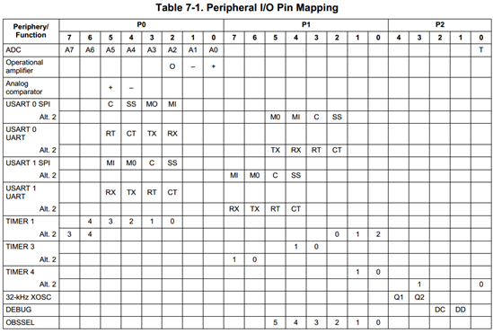
看Pin Mapping,Timer3是用的P1的端口,和P0口没有关系,先排除其他代码的问题。
你的原因,应该是对P0.4的复用引起的。而这个复用你可能无意识的,也就是对p0.4的多重的配置。在IAR里 你可以用shift+ctrl+F来查看,你对P0.4的引用情况。输入法保证在英文下使用,最好点上match case 区分大小写
谢谢各位,是管脚不同,影响的外围电路不同造成的。
是硬件问题,谢谢