AIC3254使用的一些问题
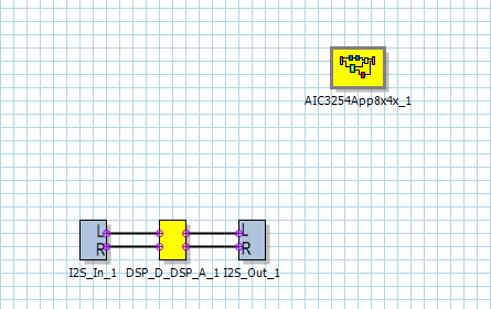
以下图片是我的GDE设置,输入的IIS 4个信号正常,现在没IIS_DATA输出. 在我的设计里,AIC3254作为miniDSP使用,工作过程:IIS输->DSP信号处理->IIS输出
以下是我的初始化代码:
/* 自恢复软复位 */
const reg_value aic3254_cReset[]=
{
0,0,
1,1
};
/* 电源设置 */
const reg_value aic3254_pSet[]=
{
{ 0,0x01},
// # reg[ 1][ 1] = 0x08 ; Power up AVDD LDO; Disable weak AVDD to DVDD connection; Enable Master Analog Power Control, AVDD LDO Powered; Disable weak AVDD to DVDD connection
{ 1,0x08},
// # reg[ 1][ 2] = 0x00 ; Enable Master Analog Power Control
{ 2,0x01},
// # reg[ 1][ 71] = 0x32 ; Set the input power-up time to 3.1ms
{ 71,0x32},
// # reg[ 1][123] = 0x01 ; Set REF charging time to 40ms (automatic)
{123,0x01},
};
/* AIC3254基础寄存器 */
const reg_value aic3254_bass[]=
{
{ 0,0x00},
// # reg[ 0][ 60] = 0x80 ; DAC prog Mode: miniDSP_A and miniDSP_D ARE powered up together, miniDSP_A used for signal processing
{ 60,0x80},
// # reg[ 0][ 61] = 0x00 ; SynchMode is disabled; DAC prog Mode: miniDSP_A and miniDSP_D NOT powered up together, miniDSP_A used for signal processing; Use miniDSP_A for signal processing
{ 61,0x00},
// # reg[ 0][ 17] = 0x08 ; 8x Interpolation
{ 17,0x08},
// # reg[ 0][ 23] = 0x04 ; 4x Decimation
{ 23,0x04},
//
{ 15,0x03},
//
{ 16,0x88},
//
{ 21,0x03},
//
{ 22,0x88},
{ 0,0x08},
// # reg[ 8][ 1] = 0x04 ; adaptive mode for ADC
{ 1,0x04},
{ 0,0x2C},
// # reg[ 44][ 1] = 0x04 ; adaptive mode for DAC
{ 1,0x04},
{ 0,0x00},
// # reg[ 0][ 4] = 0x00 ;
{ 4,0x00},
// # reg[ 0][ 11] = 0x81 ; NDAC = 1, divider powered on
{ 11,0x81},
// # reg[ 0][ 12] = 0x81 ; MDAC = 1, divider powered on
{ 12,0x81},
// # reg[ 0][ 13] = 0x02 ; DOSR = 512 (MSB)
{ 13,0x02},
// # reg[ 0][ 14] = 0x00 ; DOSR = 512 (LSB)
{ 14,0x00},
// # reg[ 0][ 18] = 0x81 ; NADC = 1, divider powered on
{ 18,0x81},
// # reg[ 0][ 19] = 0x81 ; MADC = 8, divider powered on
{ 19,0x81},
// # reg[ 0][ 20] = 0x80 ; AOSR = 128
{ 20,0x80},
// # reg[ 0][ 27] = 0x3c ; Audio Interface = IIS, Audio Data Word = 32bit, BCLK Direction Control = output,WCLK Direction = output, DOUT High Impendance = not
{ 27,0x3C},
// # reg[ 0][ 29] = 0x04 ; Bdiv_CLKIN = DAC_CLK
{ 29,0x04},
// # reg[ 0][ 30] = 0x88 ; BCLK N divider powered up, N = 8
{ 30,0x88},
// # reg[ 0][ 33] = 0x44 ; Secondary Bit Clock = Generated Primary Bit Clock,Secondary Word Clock output = Generated DAC_FS
{ 33,0x44},
// # reg[ 0][ 52] = 0x20 ; GPIO output is CLKOUT
{ 52,0x20},
// # reg[ 0][ 55] = 0x14 ; MISO is Secondary Word Clock for Audio Interface
{ 55,0x14},
{ 0,0x01},
// # reg[ 1][ 51] = 0x40 ; Mic Bias enabled, Source = Avdd, 1.25V
{ 51,0x40},
// # reg[ 1][ 52] = 0x40 ; Route IN2L to LEFT_P with 10K input impedance; Route CM1L to LEFT_M with 10K input impedance; Route IN2R to RIGHT_P with 10K input impedance; Route IN1L to LEFT_P with 10K input impedance
{ 52,0x40},
// # reg[ 1][ 54] = 0x40 ; Route CM1L to LEFT_M with 10K input impedance
{ 54,0x40},
// # reg[ 1][ 55] = 0x40 ; Route IN1R to RIGHT_P with 10K input impedance
{ 55,0x40},
// # reg[ 1][ 57] = 0x40 ; Route CM1R to RIGHT_M with 10K input impedance
{ 57,0x40},
// # reg[ 1][ 59] = 0x00 ; Enable MicPGA_L Gain Control, 0dB
{ 59,0x00},
// # reg[ 1][ 60] = 0x00 ; Enable MicPGA_R Gain Control, 0dB
{ 60,0x00},
{ 0,0x00},
// # reg[ 0][ 81] = 0xc0 ; Power up LADC/RADC
{ 81,0xC0},
// # reg[ 0][ 82] = 0x00 ; Unmute LADC/RADC
{ 82,0x00},
{ 0,0x01},
// # reg[ 1][ 20] = 0x25 ; De-pop: 5 time constants, 6k resistance
{ 20,0x25},
// # reg[ 1][ 12] = 0x08 ; Route LDAC to HPL
{ 12,0x08},
// # reg[ 1][ 13] = 0x08 ; Route RDAC to HPR
{ 13,0x08},
// # reg[ 1][ 14] = 0x08 ; Route LDAC to LOL
{ 14,0x08},
// # reg[ 1][ 15] = 0x08 ; Route LDAC to LOR
{ 15,0x08},
{ 0,0x00},
// # reg[ 0][ 63] = 0xd4 ; Power up LDAC/RDAC w/ soft stepping
{ 63,0xD4},
{ 0,0x01},
// # reg[ 1][ 16] = 0x00 ; Unmute HPL driver, 0dB Gain
{ 16,0x00},
// # reg[ 1][ 17] = 0x00 ; Unmute HPR driver, 0dB Gain
{ 17,0x00},
// # reg[ 1][ 18] = 0x00 ; Unmute LOL driver, 0dB Gain
{ 18,0x00},
// # reg[ 1][ 19] = 0x00 ; Unmute LOR driver, 0dB Gain
{ 19,0x00},
// # reg[ 1][ 9] = 0x3c ; Power up HPL/HPR and LOL/LOR drivers
{ 9,0x3C},
{ 0,0x00},
// # reg[ 0][ 64] = 0x00 ; Unmute LDAC/RDAC
{ 64,0x00}
};
const reg_value miniDSP_A_reg_values[] = {
内容由GDE生成
};
#define miniDSP_A_reg_values_COEFF_START 0
#define miniDSP_A_reg_values_COEFF_SIZE 42
#define miniDSP_A_reg_values_INST_START 42
#define miniDSP_A_reg_values_INST_SIZE 29
const reg_value miniDSP_D_reg_values[] = {
内容由GDE生成
};
AIC提供IIS时钟,主机在IIS上作为从机,只输出DATA,目前主机到AIC3254的DATA是正常的